Physics · Ch 2 — Electrostatic Potential and Capacitance
Energy Stored in a Capacitor
Energy Stored in a Capacitor
Why Does a Capacitor Store Energy?
A capacitor stores electrostatic potential energy. This energy is the work done to assemble the charges on its plates against the repulsive forces that build up as the capacitor charges.
The Derivation: Work Done in Charging
- Initial State: Consider two uncharged conductors. We will transfer charge bit by bit from conductor 2 to conductor 1.
- Intermediate State: At some point, conductor 1 has charge and conductor 2 has charge . The potential difference between them is , where is the capacitance.
- Infinitesimal Work: To transfer a tiny additional charge from conductor 2 to conductor 1, the work done is:
- Total Work (Integration): The total work to charge the capacitor from to is found by integrating:
- Energy Stored: Since the electrostatic force is conservative, this work is stored as potential energy of the system. The result is independent of how the charge is assembled.
Energy Stored in the Electric Field
The energy is not just a property of the charges; it is stored in the electric field between the plates.
- For a parallel plate capacitor with plate area and separation , the capacitance is .
- The surface charge density is , and the electric field between the plates is .
- Substituting these into gives:
- Since is the volume of the region between the plates (where the field exists), the energy density (energy per unit volume) is:
- Important: This result for energy density is general and holds for any configuration of charges, not just parallel plates.
Worked Example (NCERT Example 2.10)
(a) Charging a Capacitor:
A capacitor is charged by a battery.
- Charge stored: .
- Energy stored: .
(b) Redistribution of Charge:
The charged capacitor is disconnected from the battery and connected to an identical, uncharged capacitor.
- By charge conservation, the total charge is shared equally. Each capacitor ends up with . …
Drawn by us to help you understand the concept clearly, and verified to make sure it's accurate. For exams, practice from your textbook's own diagram.
What the Figure Shows
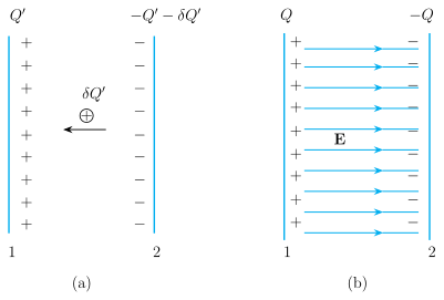
The figure has two panels, (a) and (b), each depicting a parallel-plate capacitor.
Panel (a) shows an intermediate step during the charging process. The left plate (conductor 1) has a charge (shown as a column of '+' signs). The right plate (conductor 2) has a charge (shown as a column of '−' signs). A short horizontal arrow points from the right plate to the left plate, labelled with a circled-plus symbol and the label . This arrow represents the transfer of a small positive charge from conductor 2 to conductor 1.
Panel (b) shows the fully charged capacitor. The left plate has charge and the right plate has charge . Several horizontal field lines, labelled , run from the positive plate to the negative plate, representing the uniform electric field between them.
The Physical Idea
The figure illustrates the conceptual process of building up charge on a capacitor. Starting from uncharged plates, we imagine transferring infinitesimal amounts of positive charge from the negative plate to the positive plate, one step at a time. At each intermediate stage (panel a), the plates already hold charges and , so a potential difference exists. To transfer the next bit of charge against this potential difference, external work must be done. The total work done in all these steps is the energy stored in the capacitor. Panel (b) shows the final result: the stored energy can be thought of as residing in the electric field between the plates.
Key Formulas Developed from This Figure
The work done in a single small step (panel a) is:
where:
- is the infinitesimal work done in that step.
- is the potential difference between the plates at that intermediate stage.
- is the capacitance of the capacitor.
- is the small amount of charge transferred.
Integrating this expression from to gives the total work (and hence the stored energy ):
This result can be rewritten in equivalent forms (panel b):
where:
- is the final charge on the positive plate.
- is the final potential difference between the plates.
- is the capacitance. …