A truth table is the simplest way to show exactly what a logic gate does. Before you memorise any table, picture a light switch. The switch has two states: ON or OFF. In digital electronics, we call those states 1 (ON, high voltage) and 0 (OFF, low voltage). A logic gate is a tiny circuit that takes one or more of these 1/0 inputs and produces a single 1/0 output.
The truth table is just a complete list: for every possible combination of inputs, what output does the gate give? That's all. No hidden rules, no guesswork — it's the gate's entire behaviour written in a table.
The precise statement
A truth table for a logic gate is a tabular listing of all possible input combinations (in binary order) and the corresponding output for each combination. For a gate with n inputs, there are 2n rows.
Number of rows=2number of inputs
So a 2-input gate has 22=4 rows; a 3-input gate has 23=8 rows, and so on.
The simplest example: the NOT gate (inverter)
The NOT gate has only one input. It flips the signal: 1 becomes 0, 0 becomes 1.
| Input (A) | Output (Y) |
|---|
| 0 | 1 |
| 1 | 0 |
That's the truth table. Two rows, because 21=2. The output is always the opposite of the input.
A 2-input gate: the AND gate
The AND gate gives output 1 only when both inputs are 1. Otherwise, output is 0.
| Input A | Input B | Output Y=A⋅B |
|---|
| 0 | 0 | 0 |
| 0 | 1 | 0 |
| 1 | 0 | 0 |
| 1 | 1 | 1 |
Notice the pattern: the inputs are listed in binary counting order (00, 01, 10, 11). This is the standard way to write truth tables so you never miss a combination.
To quickly write any truth table, count in binary from 0 to 2n−1 for the inputs. That guarantees every combination appears exactly once.
Why this matters
A truth table is the definition of a logic gate. When you see a gate symbol (like the AND gate's D-shape), the truth table tells you exactly what it does. You don't need to guess or remember a vague description — the table is the complete, unambiguous behaviour.
For exam problems, you'll often be asked to:
- Write the truth table for a given gate
- Identify a gate from its truth table
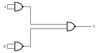
- Combine gates and produce a truth table for the whole circuit
In every case, start with the inputs, list all 2n combinations in binary order, then work out the output for each row. That's the entire method.
One more example: the OR gate
The OR gate gives output 1 if at least one input is 1.
| A | B | Y=A+B |
|---|
| 0 | 0 | 0 |
| 0 | 1 | 1 |
| 1 | 0 | 1 |