Chemistry · Ch 8 — Aldehydes, Ketones and Carboxylic Acids
Structure of the Carbonyl Group
Structure of the Carbonyl Group
Geometry of the carbonyl carbon
The carbonyl carbon atom is -hybridised. It uses its three orbitals to form three sigma () bonds — two to the substituents (R groups or hydrogen) and one to the oxygen atom. The fourth valence electron of carbon is left in an unhybridised -orbital, and this overlaps sideways with a -orbital on the oxygen atom to form a -bond. So the double bond, like a carbon-carbon double bond, is really one bond plus one bond. The oxygen atom additionally holds two non-bonding (lone) electron pairs, which are not involved in either bond.
Because the carbonyl carbon is -hybridised, it — together with the three atoms directly attached to it (the two substituents and the oxygen) — lies in a single plane, with the -electron cloud spread above and below that plane. This gives the carbonyl group a trigonal planar geometry, with bond angles of approximately , exactly as expected of any -hybridised centre.
Drawn by us to help you understand the concept clearly, and verified to make sure it's accurate. For exams, practice from your NCERT textbook's own diagram.
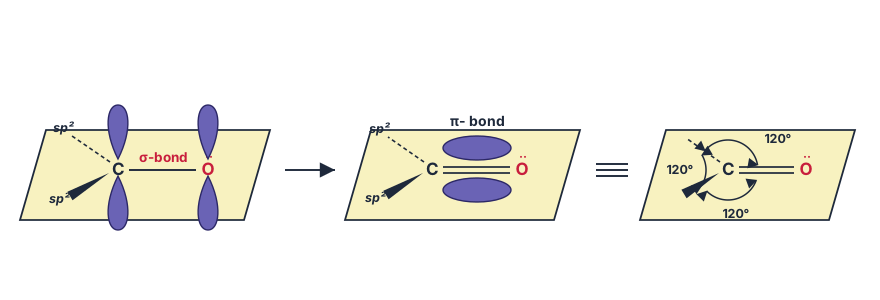
The figure presents a stepwise orbital construction of the carbonyl group (), showing how the double bond arises from atomic orbitals.
Stage 1: σ-bond framework
The carbon atom is -hybridised, giving three orbitals lying in a plane at angles. One of these orbitals overlaps head-on with an orbital from oxygen to form the σ bond (the primary bond along the internuclear axis). The remaining two orbitals on carbon are used for bonds to other atoms (e.g., two hydrogens or alkyl groups). Both carbon and oxygen also possess an unhybridised orbital perpendicular to the plane.
Stage 2: π-bond formation
The unhybridised orbitals on carbon and oxygen are parallel and overlap sideways — one lobe above the plane and one lobe below. This lateral overlap creates the π bond, which is weaker than the σ bond and restricts rotation about the axis.
Stage 3: Complete carbonyl group
The finished carbonyl has a trigonal-planar geometry around carbon: bond angles of , with the carbon doubly bonded to oxygen. Oxygen retains two lone pairs (in orbitals), making it electron-rich. The π-electron cloud is concentrated above and below the molecular plane.
Physical idea taught
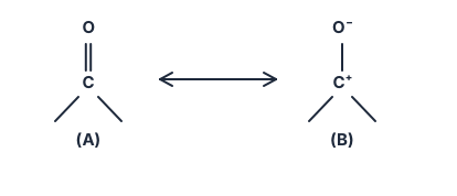
The figure explains why the carbonyl group is polar and reactive. Oxygen is more electronegative than carbon, so the π electrons are pulled toward oxygen. This polarisation is represented by resonance:
The dipolar resonance structure (B) shows a positive charge on carbon and a negative charge on oxygen. This makes the carbonyl carbon an electrophile (Lewis acid) and the carbonyl oxygen a nucleophile (Lewis base). The dipole moment of carbonyl compounds is larger than that of ethers because of this charge separation.
Key formula developed
The resonance hybrid is described by two contributing structures: …
The textbook's orbital diagram (Fig. 8.1) walks through this picture in three stages: first the three bonds around the carbon, then the sideways – overlap that forms the bond, and finally the resulting trigonal shape with its three bond angles.
Polarity of the carbonyl group
Oxygen is considerably more electronegative than carbon, so the double bond is strongly polarised: the shared electron density is pulled toward oxygen, leaving the carbonyl carbon carrying a partial positive charge and the oxygen a partial negative charge. As a direct consequence:
- The carbonyl carbon behaves as an electrophilic centre — a Lewis acid site, since it is short of electron density and can accept an incoming electron pair.
- The carbonyl oxygen behaves as a nucleophilic centre — a Lewis base site, since it carries the excess electron density (plus its two lone pairs).
This polarisation gives carbonyl compounds substantial dipole moments, and makes them noticeably more polar than ethers, which lack a -polarised double bond entirely.
The high polarity of the carbonyl group is best understood as a resonance hybrid of two contributing structures:
Drawn by us to help you understand the concept clearly, and verified to make sure it's accurate. For exams, practice from your NCERT textbook's own diagram.
Redrawn from the NCERT page with the structures, printed labels () and reagent placement exactly as the textbook prints them. Every element of this display was checked against the printed page during the sweep's blind-judge verification pass, so what …
…