Physics · Ch 4 — Moving Charges and Magnetism
Force between Two Parallel Currents, the Ampere
Force between Two Parallel Currents, the Ampere
Why Two Currents Exert a Force on Each Other
A current-carrying conductor produces a magnetic field around it (Biot-Savart law). If another current-carrying conductor is placed in that field, the Lorentz force acts on the moving charges in the second conductor. Therefore, two nearby current-carrying wires should exert magnetic forces on each other. Ampere studied this force in detail between 1820–25.
Force on One Wire Due to Another (Parallel Currents)
Consider two long, straight, parallel conductors a and b, separated by a distance . They carry steady currents and in the same direction.
- Magnetic field due to conductor 'a' at the location of 'b': Conductor 'a' produces a magnetic field at every point along conductor 'b'. Using Ampere's circuital law (or the Biot-Savart result for an infinite wire), the magnitude of this field is:
The direction of $\mathbf{B}_a$ is given by the right-hand rule. For horizontal wires with current flowing in the same direction, this field points **downwards** (perpendicular to the plane containing the wires).
2. Force on conductor 'b' due to this field:
Conductor 'b' carries current and is placed in the external field . The magnetic force on a length of conductor 'b' is given by the Lorentz force on a current-carrying wire:
Since $\mathbf{L}$ (direction of current in 'b') is perpendicular to $\mathbf{B}_a$, the magnitude is:
Substituting $B_a$:
The direction of $\mathbf{F}_{ba}$ (using the right-hand rule for cross product) is **towards conductor 'a'**. Thus, parallel currents attract.
3. Force on conductor 'a' due to 'b':
By symmetry, the force on a length of conductor 'a' due to the field of 'b' has the same magnitude:
Its direction is towards conductor 'b'. Therefore:
This satisfies Newton’s third law.
Opposite (Antiparallel) Currents
If the currents flow in opposite directions, the direction of the magnetic field at the location of the other wire reverses. Using the same cross-product rule, the force becomes repulsive.
Rule:
- Parallel currents attract.
- Antiparallel currents repel. (This is opposite to the electrostatic rule where like charges repel.)
Force Per Unit Length and the Definition of the Ampere
The magnitude of the force per unit length between two parallel wires is:
This expression is used to define the SI base unit of current, the ampere (A).
Definition of the Ampere: …
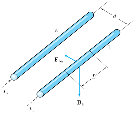
Drawn by us to help you understand the concept clearly, and verified to make sure it's accurate. For exams, practice from your NCERT textbook's own diagram.
The figure shows two long, straight, parallel cylindrical conductors drawn in a 3‑D perspective. The left/upper rod is labelled conductor ‘a’ and the right/lower rod is conductor ‘b’. Both rods run from lower‑left to upper‑right. At the lower end of each rod, an arrow indicates the direction of the steady current: in conductor ‘a’ and in conductor ‘b’. The currents are parallel (both flowing in the same direction along the rods).
A double‑headed arrow near the top of the diagram marks the perpendicular separation between the two conductors, labelled . On conductor ‘b’, a segment of length is highlighted. At the location of this segment, the magnetic field produced by conductor ‘a’ is drawn as a downward‑pointing arrow labelled . A bold arrow on conductor ‘b’ shows the force — the force on conductor ‘b’ due to conductor ‘a’ — pointing sideways toward conductor ‘a’.
Physical idea
The diagram illustrates the magnetic interaction between two parallel current‑carrying wires. Conductor ‘a’ sets up a magnetic field that encircles it (by the right‑hand rule). At the position of conductor ‘b’, this field is perpendicular to the wire and points downward (when the wires are horizontal). Conductor ‘b’, carrying current , experiences a Lorentz force due to this external field. The direction of the force is given by the right‑hand rule for a current in a magnetic field: it points toward conductor ‘a’, meaning parallel currents attract. (If the currents were antiparallel, the force would reverse to repulsion.)
Key formulas developed from this figure
The magnitude of the magnetic field produced by conductor ‘a’ at a distance is (from Ampere’s circuital law):
where is the permeability of free space.
The force on a length of conductor ‘b’ due to this field is:
…