Physics · Ch 4 — Moving Charges and Magnetism
The Moving Coil Galvanometer
The Moving Coil Galvanometer
What is a Moving Coil Galvanometer?
A moving coil galvanometer (MCG) is a device used to detect and measure small electric currents. It works on the principle that a current-carrying coil placed in a magnetic field experiences a torque. The MCG is the heart of analog ammeters and voltmeters.
Construction and Working Principle
The key parts of an MCG are:
- A rectangular coil with many turns () of wire, free to rotate about a fixed axis.
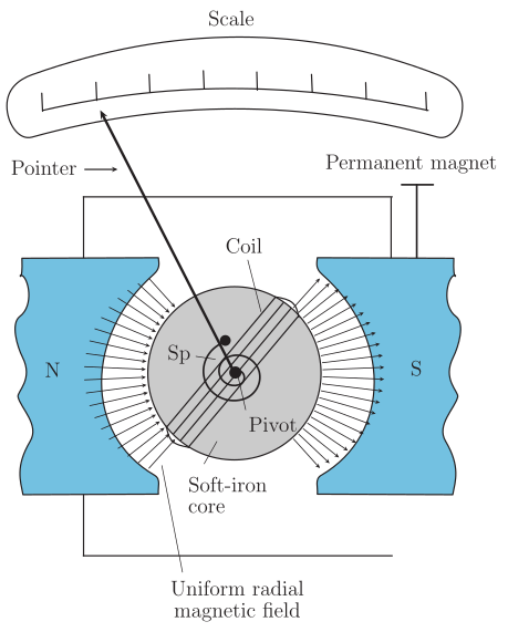
- The coil is placed in a uniform radial magnetic field. This is achieved using a cylindrical soft iron core between the poles of a permanent magnet. The iron core serves two purposes:
- It makes the magnetic field radial — meaning the field lines are always parallel to the plane of the coil and perpendicular to its length. This ensures that the angle between the magnetic field and the normal to the coil is always as the coil rotates.
- It increases the strength of the magnetic field.
- A spring () provides a restoring torque that is proportional to the twist ().
How it works:
- When a current flows through the coil, a magnetic torque acts on it.
- Because the field is radial, the torque is maximum and constant for any angular position of the coil. The magnitude of this torque is:
where:
- $N$ = number of turns in the coil
- $I$ = current flowing through the coil
- $A$ = area of the coil
- $B$ = strength of the radial magnetic field
3. This magnetic torque causes the coil to rotate. As it rotates, the spring twists and produces a restoring torque:
where:
- $k$ = torsional constant of the spring (restoring torque per unit twist)
- $\phi$ = angular deflection of the coil
4. The coil comes to rest at an equilibrium position where the magnetic torque is exactly balanced by the restoring torque:
- Rearranging this gives the deflection as a function of current :
The quantity in brackets is a constant for a given galvanometer. This shows that the deflection is **directly proportional** to the current.
Conversion to Ammeter and Voltmeter
A galvanometer cannot directly measure large currents or voltages because:
- It is very sensitive (full-scale deflection for A currents).
- It has a large resistance, which would alter the circuit's current if connected in series.
1. Converting to an Ammeter (to measure current)
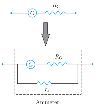
- A small resistance , called a shunt, is connected in parallel with the galvanometer coil.
- The shunt allows most of the current to bypass the delicate galvanometer coil.
- The effective resistance of the ammeter becomes very small (), so it does not significantly affect the circuit when connected in series.
- Formula for shunt resistance: The value of is chosen so that only the full-scale deflection current flows through the galvanometer when the total current to be measured is .
2. Converting to a Voltmeter (to measure voltage)
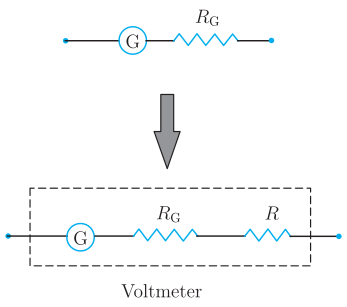
- A large resistance is connected in series with the galvanometer coil.
- This large series resistance ensures that the voltmeter draws a very small current from the circuit, so it does not disturb the voltage being measured. …
Drawn by us to help you understand the concept clearly, and verified to make sure it's accurate. For exams, practice from your NCERT textbook's own diagram.
The figure is a schematic of a moving coil galvanometer (MCG). At the top, a curved scale with tick marks is shown, and a pointer extends from a central pivot up to the scale to indicate the deflection angle . In the centre, a rectangular coil (shaded cylindrical body) is placed in the gap between two curved magnetic pole-pieces: N (north pole, left) and S (south pole, right, blue). These form the permanent magnet. Inside the coil is a cylindrical soft-iron core, which makes the magnetic field radial and increases its strength. A pivot at the centre allows the coil to rotate freely. A spring labelled Sp provides a restoring torque. Radial arrows in the gap represent the uniform radial magnetic field — this design ensures that the plane of the coil is always parallel to the field, so the angle between the field and the coil’s normal is always ().
The physical idea is that when a current flows through the coil, a magnetic torque acts on it. This torque is balanced by the spring’s restoring torque, giving a steady deflection proportional to the current. The key formula derived from this figure is:
where:
- = torsional constant of the spring (restoring torque per unit twist)
- = steady angular deflection of the pointer
- = number of turns in the coil
- = current through the coil
- = area of the coil
- = magnitude of the radial magnetic field
Rearranging gives the deflection as a function of current:
…
Drawn by us to help you understand the concept clearly, and verified to make sure it's accurate. For exams, practice from your NCERT textbook's own diagram.
What the Figure Shows
The figure is a schematic diagram with two panels, arranged vertically.
Top panel: A simple circuit branch containing a galvanometer (G) represented as a circle labelled 'G'. Beside it is a zig-zag symbol representing the galvanometer's own coil resistance, labelled . This is the bare galvanometer before any modification.
Bottom panel: The same galvanometer (G and ) is now connected in parallel with a small resistor labelled , drawn as a separate branch below the galvanometer. The entire combination — the galvanometer and the shunt resistor together — is enclosed in a dashed box labelled 'Ammeter'. A thick grey downward arrow between the two panels indicates the conversion process: from a sensitive galvanometer to a practical ammeter.
The Physical Idea
A galvanometer is too sensitive (full deflection for microamperes) and has too high a resistance to be placed directly in series in a circuit for measuring large currents. To convert it into an ammeter, a shunt resistance of very small value is connected in parallel with the galvanometer coil. This shunt diverts most of the current away from the delicate galvanometer, allowing only a small, measurable fraction to pass through the coil. The parallel combination has a very low equivalent resistance, so inserting it into a circuit causes negligible disturbance to the original current.
Key Formula
The textbook derives the condition for the shunt using the current division rule. If is the total current to be measured and is the full-scale deflection current of the galvanometer, then the current through the shunt is . Since the galvanometer and shunt are in parallel, the voltage across each is the same:
Rearranging gives the required shunt resistance:
Here:
- = resistance of the galvanometer coil
- = current for full-scale deflection of the galvanometer …
Drawn by us to help you understand the concept clearly, and verified to make sure it's accurate. For exams, practice from your NCERT textbook's own diagram.
The figure shows two circuit diagrams arranged vertically. The top diagram is a simple loop: a galvanometer, represented by the letter G inside a circle, is connected in series with a zig-zag symbol representing its own coil resistance . A thick grey arrow pointing downward indicates that this is the original galvanometer — a sensitive current-detecting device.
The bottom diagram shows the conversion of that same galvanometer into a voltmeter. The galvanometer (G with ) is now connected in series with a second zig-zag resistor labelled R, which is drawn larger to indicate it has a large value. The entire series combination — G, , and R — is enclosed in a dashed box labelled Voltmeter. This box represents the complete instrument that will be placed across a circuit element to measure voltage.
The physical idea is that a voltmeter must draw very little current so it does not disturb the circuit it measures. By adding a large series resistance , the total resistance of the voltmeter becomes (since ). This high resistance limits the current through the galvanometer to a tiny value, allowing the pointer deflection to be proportional to the voltage across the voltmeter terminals.
The key formula developed from this figure is the voltage sensitivity of the converted voltmeter. From the galvanometer's deflection equation:
where:
- = angular deflection of the pointer
- = number of turns in the coil
- = area of the coil
- = radial magnetic field strength
- = torsional constant of the spring
- = current through the galvanometer
For the voltmeter, the current through the galvanometer is , where is the voltage being measured. Substituting gives the voltage sensitivity: …