Q.Consider the two idealized systems:
Concept understanding — Magnetic Field Lines
Magnetic Field Lines
A magnet or a current-carrying wire fills the space around it with a magnetic field. We cannot see this field, so we picture it using magnetic field lines — continuous curves that map both the direction and the strength of the field at every point.
What a field line represents
The tangent to a field line at any point gives the direction of the magnetic field B there. If you place a tiny compass needle at that point, it aligns along the tangent, its north pole pointing the way the line runs. The density of the lines (how closely packed they are) represents the magnitude of B: crowded lines mean a strong field, widely spaced lines mean a weak field.
Key properties (exam essentials)
- Outside a magnet the lines run from the north pole to the south pole, but they are continuous closed loops — inside the magnet they run south to north, so every line closes on itself.
- Two field lines never intersect. If they did, a compass at the crossing point would have to point in two directions at once, which is impossible.
- Lines are crowded where the field is strong (near the poles) and spread out where it is weak.
- They form smooth, continuous curves with no free ends.
The fact that magnetic field lines always close on themselves is deep: it means there are no isolated magnetic poles (monopoles). This is Gauss's law for magnetism:
∮B⋅dA=0
The net magnetic flux through any closed surface is zero — every line that enters the surface also leaves it.
Contrast with electric field lines
Electric field lines start on positive charges and end on negative charges — they are open curves. Magnetic field lines have no such start or end; they are always closed loops. This single difference reflects that isolated electric charges exist, but isolated magnetic poles do not.
Uniform field
When field lines are parallel, equally spaced, and straight, the field is uniform — the same magnitude and direction everywhere. The region deep inside a long solenoid, or between the flat poles of a large magnet, is very nearly uniform.
Why this matters
Field-line diagrams let you read a field at a glance: where it is strong, which way it points, and whether it is uniform. They underpin magnetic flux, ΦB=B⋅A, Gauss's law for magnetism, and the study of electromagnetic induction. Sketching the correct pattern for a bar magnet, a straight wire (concentric circles around it), and a solenoid (uniform inside, bar-magnet-like outside) is a standard exam skill.
The properties of magnetic field lines, including why they always form closed loops, are introduced in the NCERT Class 12 Physics chapter on magnetism and matter, and "properties of magnetic field lines class 12 physics important questions" is a common CBSE board short-answer topic. This closed-loop explanation, linked to the absence of magnetic monopoles, matches the NCERT-prescribed reasoning.
Why this formula?
Magnetic Field Lines
A magnetic field line is an imaginary curve we draw to picture an invisible field. Its purpose is to encode two things at once: the direction of the field B (the tangent to the line at any point) and the strength of the field (how densely the lines are packed). They are a map, not physical objects.
The four defining rules
1. The tangent gives the field direction. At every point, B points along the tangent to the field line through that point. A compass needle placed on the line aligns with it.
2. Field lines form closed loops. Unlike electric field lines, which begin and end on charges, magnetic field lines never start or stop. This is Gauss's law for magnetism:
∮B⋅dA=0
The net flux through any closed surface is zero because isolated magnetic poles (monopoles) do not exist — every north pole is paired with a south pole. So for a bar magnet the lines emerge from the north pole outside, curve around to the south pole, and continue through the interior of the magnet back to the north, closing the loop.
3. Field lines never cross. If two lines crossed, the tangent — and hence B — would have two directions at that point. Since the field has a single, unique direction everywhere, crossings are impossible.
4. Density represents strength. Where lines are crowded, the field is strong; where they spread out, it is weak. The flux through a small perpendicular area dA is dΦB=BdA, so packing more lines through the same area means a larger B (as near the poles of a magnet).
A quick picture
For a straight wire carrying current I, the field lines are concentric circles around the wire, tightly spaced close to the wire and spreading out farther away. Grip the wire with your right hand, thumb along the current — your curled fingers trace the direction of the loops. This is exactly the closed-loop, non-crossing, density-encodes-strength behaviour the rules above describe.
The abrupt-cut-off idealisations cannot be exact. The capacitor field is consistent with Gauss's law, but a loop crossing its boundary violates ∮E⋅dl=0, so (a) and (c) are wrong. For the solenoid, B=0 outside makes a Gaussian surface at the end have net magnetic flux (violating ∇⋅B=0) and an external Amperian loop enclosing the winding current gives ∮H⋅dl=0=Ien.
Correct options: (b) and (d) — case (ii) contradicts both Gauss's law for magnetism and Ampère's law.
Sharp cut-off fields are unphysical. The solenoid idealisation (B uniform inside, exactly zero outside) violates Gauss's law for magnetism and Ampère's law. Correct options: (b) and (d).
Concept understanding.
Case (i) — capacitor: Taking E uniform between the plates and zero outside is consistent with Gauss's law (a pill-box's flux still equals qenc/ε0), so (a) is wrong. But a loop running from inside (where E=0) to outside (where E=0) would give ∮E⋅dl=0, contradicting the electrostatic condition ∮E⋅dl=0. Hence (c) is wrong — case (i) does not agree with that law, it violates it (which is exactly why fringing fields must exist).
Case (ii) — solenoid: If B were exactly zero outside, a closed Gaussian surface straddling the end face would have flux entering (inside, B=0) with none leaving, giving net ∮B⋅dA=0 and violating Gauss's law for magnetism ∇⋅B=0 (field lines must close). So (b) is correct. Similarly, an Amperian loop encircling the solenoid from outside encloses the net winding current, yet B=0 there would give ∮H⋅dl=0, contradicting ∮H⋅dl=Ien. So (d) is correct.
(b) case (ii) contradicts Gauss's law for magnetic fields and (d) case (ii) contradicts ∮H⋅dl=Ien. (a) is false, and (c) is false because case (i) actually violates ∮E⋅dl=0 rather than agreeing with it.
Method: Testing an Idealized Field Against Gauss's and Ampere's Laws
Use this method whenever a problem presents an idealized field (sharp cutoff at a boundary: uniform inside a bounded region, exactly zero immediately outside) and asks which fundamental law that idealization actually violates.
Steps
Step 1: State the idealization precisely
Write down exactly what is assumed uniform and where it is assumed to drop to zero — e.g. "field is constant inside a bounded region and exactly zero immediately outside it, with no transition region."
Step 2: Test against Gauss's law for the relevant field
For E: a Gaussian surface drawn entirely inside, or entirely outside, the region gives flux equal to enclosed charge over ε0 — a sharp uniform-then-zero field is often still consistent with this, since it correctly reflects the enclosed charge. For B: a Gaussian surface straddling the boundary (e.g. a pillbox capping the end of a solenoid) has flux entering through one face with none leaving anywhere else if B=0 just outside — that gives a nonzero net flux, which violates ∇⋅B=0, since real B field lines must always close on themselves.
Step 3: Test against the relevant circulation law
For electrostatics: draw a closed loop running from a region of nonzero E into a region of zero E. The electrostatic condition ∮E⋅dl=0 must hold for ANY closed loop — if the sharp idealization makes this loop integral come out nonzero, it violates that condition (this is exactly why real fringing fields must exist at the edges). For magnetism: an Amperian loop that encloses the true winding current but passes through the idealized "zero field" region outside gives ∮H⋅dl=0 from that region's contribution, contradicting ∮H⋅dl=Ien when the enclosed current is genuinely nonzero.
Step 4 (Applying to this problem): Separate "is consistent with" from "agrees with"
Distinguish a law the idealization happens to satisfy on a bulk Gaussian surface from a circulation-type law it silently violates through the artificial sharp edge. A field can pass one test and fail the other — always check flux-type and circulation-type laws separately rather than assuming one violation implies the other.
- TG EAPCET 2024Set eng-2024-05-09-FN1 markMCQQ.The most exotic diamagnetic materials are (A) Superconductors (B) Semiconductors (C) Conductors (D) Resistors
›Reveal solutionSolution
Diamagnetism arises from induced currents opposing an applied field; superconductors exhibit perfect diamagnetism (Meissner effect), expelling all magnetic flux, making them the most exotic diamagnetic materials. The correct option is (A).
The key concept here is diamagnetism — a property where a material creates an induced magnetic field in the opposite direction to an applied external field, causing repulsion. While all materials have some diamagnetic response, it is usually weak and overshadowed by paramagnetism or ferromagnetism. The "most exotic" case occurs when diamagnetism is perfect and complete, meaning the material expels all magnetic flux from its interior.
-
Understand the Meissner effect in superconductors
When a superconductor is cooled below its critical temperature, it not only loses electrical resistance but also actively expels any magnetic field from its interior. This is the Meissner effect, a hallmark of superconductivity. The result is perfect diamagnetism: the magnetic susceptibility χ=−1 (in SI units, the relative permeability μr=0). No other material achieves this — ordinary diamagnets like bismuth or water have χ≈−10−5 to −10−4.
-
Compare with other options
- (B) Semiconductors: These are typically diamagnetic or weakly paramagnetic, but their susceptibility is tiny (e.g., silicon χ≈−3.9×10⁻⁶). Not exotic.
- (C) Conductors: Normal metals (e.g., copper, silver) are diamagnetic due to core electrons, but their susceptibility is also small (χ∼−10−5). They do not expel fields.
- (D) Resistors: This is a circuit component, not a material class. Resistors are made from conductors or semiconductors, so they inherit ordinary diamagnetism at best.
-
Why superconductors are "most exotic"
The perfect diamagnetism of superconductors is a macroscopic quantum phenomenon — it arises from the formation of Cooper pairs and the London penetration depth. It is not just strong; it is complete and persistent, even in the presence of strong fields (up to a critical value). This makes superconductors the only known materials that can levitate a magnet above them, a direct demonstration of extreme diamagnetism.
Watch outA common pitfall is confusing "diamagnetic" with "non-magnetic." All materials are diamagnetic at some level, but only superconductors show perfect diamagnetism. Also, note that "conductors" like copper are diamagnetic, but their effect is negligible compared to superconductors.
TipA neat way to remember: The Meissner effect is the "super" in superconductor's diamagnetism — it's not just low resistance, it's magnetic field expulsion.
✓Final answerThe correct option is (A).
ANSWER: A
-
- TG EAPCET 2024Set eng-2024-05-10-AN1 markMCQQ.An electron falling freely under the influence of gravity enters a uniform magnetic field directed towards south. The electron is initially deflected towards (A) east (B) west (C) north (D) south
›Reveal solutionSolution
Taking down =−z^, south =−y^, east =+x^: v×B points west, and the electron's negative charge flips the force to east — option (A).
Concept. The magnetic force on a charge is F=qv×B. For an electron q=−e, so the force is opposite to v×B.
Set up axes. East =+x^, North =+y^, Up =+z^. Then
- Velocity (falling): v=−vz^,
- Field (south): B=−By^.
Cross product.
v×B=(−vz^)×(−By^)=vB(z^×y^)=vB(−x^)=−vBx^,
using z^×y^=−x^. This points west.
Include the electron's charge.
F=(−e)(−vBx^)=+evBx^,
which points along +x^= east.
✓Final answerThe electron is deflected towards east — the correct option is (A).
ANSWER: A
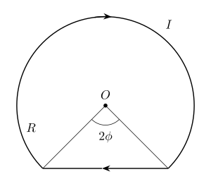
- TG EAPCET 2022Set eng-2022-07-18-FN1 markMCQQ.A current I = 5A flows along a thin wire shaped as shown in figure. The radius of curved part of the wire is equal to R = 100 mm, the angle 2ϕ = 90°. The magnitude of magnetic field at the point O is approximately [FIGURE] [Use 4πμ0=10−7 TmA−1] (A) 33.6 μT (B) 38.4 μT (C) 48.7 μT (D) 25.2 μT
›Reveal solutionSolution
Superpose the arc (θ=2π−2ϕ at the centre) and the straight chord (perpendicular distance Rcosϕ): B=4πRμ0I(2π−2ϕ+2tanϕ)≈33.6 μT — option (A).
The concept first
Biot–Savart is linear, so a bent wire is handled by chopping it into pieces whose field you already know and adding. Two standard results are all you need:
- Circular arc of radius R subtending angle θ (radians) at its centre:
B=4πRμ0Iθ.
(Check: θ=2π recovers the full loop, B=μ0I/2R.)
- Finite straight wire at perpendicular distance d, with the ends seen at angles α1,α2 from the foot of the perpendicular:
B=4πdμ0I(sinα1+sinα2).
The final, and easily missed, step is direction: here the current runs clockwise round the arc and clockwise along the chord as seen from the page, so both fields point into the page at O and the magnitudes simply add. (If they opposed, we would subtract.)
Step-by-step
- Contribution of the arc. The two radii from O to the arc's ends enclose the angle 2ϕ at the bottom; the wire's arc is therefore the major arc, subtending
θ=2π−2ϕ.
Barc=4πRμ0I(2π−2ϕ).
- Geometry of the straight chord. The chord joins the two arc ends. Drop a perpendicular from O to it: since each radius makes an angle ϕ with that perpendicular, the perpendicular distance is
d=Rcosϕ,
and the chord's half-length is Rsinϕ.
- Contribution of the chord. Each half of the chord subtends, at the foot of the perpendicular, an angle whose sine is
sinα=(Rsinϕ)2+(Rcosϕ)2Rsinϕ=sinϕ.
Both halves contribute equally, so
Bstraight=4π(Rcosϕ)μ0I(sinϕ+sinϕ)=4πRμ0I⋅cosϕ2sinϕ=4πRμ0I(2tanϕ).
- Add (both into the page).
B=4πRμ0I(2π−2ϕ+2tanϕ).
- Insert the numbers. 2ϕ=90∘⇒ϕ=45∘=π/4, tan45∘=1:
2π−2(4π)+2(1)=6.2832−1.5708+2=6.7124.
And the prefactor, with I=5 A, R=100 mm=0.1 m:
4πRμ0I=0.1(10−7)(5)=5×10⁻⁶ T.
- Evaluate.
B=(5×10⁻⁶)(6.7124)=3.356×10⁻⁵ T≈33.6 μT.
- Sanity check. A complete loop alone would give 2Rμ0I=0.24π×10−7×5≈31.4 μT. Our wire is a loop with a quarter cut out (which removes ≈7.9 μT) but with a chord added back (which adds 10 μT), netting slightly more than the full loop — and 33.6 μT is indeed slightly more. Consistent.
✓Final answerThe total field at O is 4πRμ0I(2π−2ϕ+2tanϕ)≈33.6 μT — option (A).
ANSWER: A
🎓Unlock everything free for 14 days
- ✓Full step-by-step solutions
- ✓Concept-first explanations
- ✓Methods, shortcuts & mistakes
- ✓PYQ mapping + timed mock tests
Full access for 14 days. No credit card required.