Physics · Ch 2 — Ray Optics and Optical Instruments
The Mirror Equation
The Mirror Equation
The Mirror Equation: Connecting Object Distance, Image Distance, and Focal Length
The mirror equation is the fundamental relationship that links three key distances for any spherical mirror (concave or convex):
- Object distance () – distance of the object from the pole of the mirror.
- Image distance () – distance of the image from the pole.
- Focal length () – distance of the focus from the pole.
It is derived using geometry and the laws of reflection, assuming paraxial rays (rays that make small angles with the principal axis).
Derivation in Steps
-
Set up the geometry
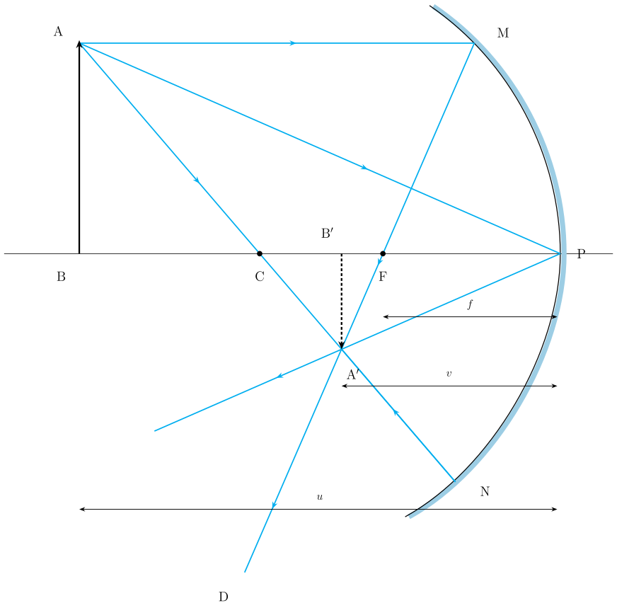
Consider a concave mirror forming a real, inverted image of an object. Two similar right-angled triangles are identified:
- and (for paraxial rays, is nearly perpendicular to ).
- and (because ).
-
Relate distances using similarity
From the first pair:
Since , this becomes:
From the second pair:
- Combine the ratios Equating the right-hand sides of (9.4) and (9.5):
Using , we get:
-
Apply the Cartesian sign convention
Light travels from object to mirror — this direction is taken as positive.
To reach the object (), image (), and focus () from the pole (), we travel opposite to the incident light. Hence:
Substituting into (9.6):
Simplifying:
Cross-multiplying:
Divide both sides by :
- The mirror equation Rearranging gives the standard form:
This is valid for all spherical mirrors (concave or convex) and for both real and virtual images, provided the sign convention is followed.
Linear Magnification ()
Magnification tells us how the image size compares to the object size.
- Definition:
where = image height, = object height (both with sign).
- Relation to distances: From similar triangles and :
Hence:
…
Drawn by us to help you understand the concept clearly, and verified to make sure it's accurate. For exams, practice from your textbook's own diagram.
Figure 9.5: Ray Diagram for a Concave Mirror — Object Beyond C
The figure shows a concave mirror drawn as an arc opening to the left, with its reflecting surface on the right side of the diagram. A horizontal line through the centre of the mirror is the principal axis. On this axis, three key points are marked from left to right: the pole (at the mirror's vertex), the focus , and the centre of curvature . The distance is the focal length , and is the radius of curvature .
An object is represented by an upright arrow , with its base on the principal axis and its tip above the axis. The object is placed beyond (to the left of ). From point , three special rays are drawn:
- A ray parallel to the principal axis, which after reflection passes through .
- A ray passing through , which strikes the mirror normally and retraces its path back through .
- A ray passing through , which after reflection becomes parallel to the principal axis.
These three reflected rays converge at a single point on the left side of the mirror, between and . From , a perpendicular is dropped to the principal axis, meeting it at . The image is a downward-pointing arrow — real, inverted, and diminished (smaller than the object).
Physical Idea Taught
The diagram illustrates the mirror equation and magnification formula for a concave mirror when the object is beyond . It shows that:
- The image is real (rays actually meet), inverted, and smaller than the object.
- The image lies between and .
- The geometry of similar triangles ( and ) leads directly to the mirror equation.
Key Formulas Derived from This Figure
Using the sign convention (incident light direction is positive, so distances to object, image, and focus are negative for a concave mirror), the textbook derives:
Mirror equation:
where:
- = object distance from pole (negative, here ) …
Drawn by us to help you understand the concept clearly, and verified to make sure it's accurate. For exams, practice from your textbook's own diagram.
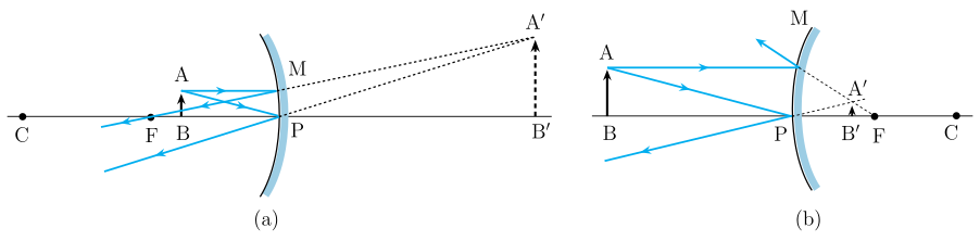
Figure 9.6 consists of two separate ray diagrams, labeled (a) and (b), each showing how a spherical mirror forms a virtual image.
Panel (a): Concave mirror with object between P and F
- The mirror is concave, with its reflecting surface on the left. The principal axis is a horizontal line through the centre.
- Labels: Pole P, focus F, centre of curvature C (all on the principal axis). The object AB is an upright arrow placed between P and F (i.e., object distance ).
- Two rays are drawn from point A of the object:
- A ray parallel to the principal axis — after reflection, it passes through F.
- A ray directed toward C (or through F) — after reflection, it becomes parallel to the axis.
- After reflection, these rays diverge (they move apart). Their backward extensions (shown as dashed lines) meet behind the mirror at point A′.
- The image A′B′ is:
- Virtual (rays do not actually meet; only their extensions do),
- Erect (same orientation as object),
- Magnified (larger than object).
- The image lies behind the mirror, between P and F on the virtual side.
Panel (b): Convex mirror
- The mirror is convex, with its reflecting surface on the left. The principal axis is again horizontal.
- Labels: P, F, C (for a convex mirror, F and C lie behind the mirror). The object AB is an upright arrow placed in front of the mirror (any distance).
- Two rays from point A:
- A ray parallel to the principal axis — after reflection, it appears to come from F behind the mirror.
- A ray directed toward C (behind the mirror) — after reflection, it retraces its path.
- The reflected rays diverge; their dashed backward extensions meet behind the mirror at A′.
- The image A′B′ is:
- Virtual,
- Erect,
- Diminished (smaller than object),
- Located between P and F behind the mirror.
Physical idea taught by the figure
The figure illustrates that virtual images are formed when reflected rays diverge — the brain “sees” the image where the rays appear to come from. For a concave mirror, this happens only when the object is closer than the focus (between P and F). For a convex mirror, it happens for any object position — the image is always virtual, erect, and diminished.
Key formula(s) developed with this figure
The mirror equation and magnification formula are derived using similar triangles from ray diagrams (like Fig. 9.5) and are valid for both real and virtual images (including those in Fig. 9.6):
- = object distance (negative when object is in front of mirror, as per sign convention)
- = image distance (negative for real images in front, positive for virtual images behind) …