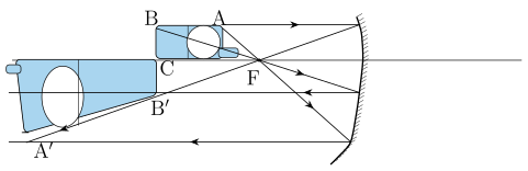
Q.A mobile phone lies along the principal axis of a concave mirror, as shown in Fig. 9.7. Show by suitable diagram, the formation of its image. Explain why the magnification is not uniform. Will the distortion of image depend on the location of the phone with respect to the mirror?
Concept understanding — Spherical Mirror Equation
The Spherical Mirror Equation: From Intuition to Formula
Imagine you're standing in front of a concave mirror — the kind that makes your face look bigger when you're close, but flips everything upside down when you step far back. That change isn't magic; it's geometry. The spherical mirror equation is the single relationship that predicts exactly where an image will form, and whether it's real or virtual, for any spherical mirror.
The Core Idea
Every point on an object sends out light rays in all directions. A mirror redirects those rays. The mirror equation tells you: given the mirror's curvature and the object's distance, where will those rays meet again (or appear to meet)?
There are only three quantities you need:
- u — object distance (from the mirror's pole)
- v — image distance (from the mirror's pole)
- f — focal length (a property of the mirror's curvature)
The equation is:
v1+u1=f1
The power is in the sign convention, because every distance can point in one of two directions.
The Sign Convention (New Cartesian Sign Convention)
This is where most students slip. The equation works for all spherical mirrors — concave and convex — only if you follow the convention used throughout NCERT and CBSE:
- All distances are measured from the mirror's pole.
- The incident light is taken to travel left to right, so distances measured in that same direction (to the right) are positive, and distances measured against it (to the left) are negative.
- Heights above the principal axis are positive; heights below are negative.
Because a real object is always placed in front of the mirror (to the left, where the incident light originates), its distance u is always negative.
Under this convention, the focal length of a concave mirror is negative (its focus F sits in front of the mirror, on the same side as the object), and the focal length of a convex mirror is positive (its focus lies behind the mirror). This is one of the most frequently tested facts in CBSE board exams.
A very common mistake is writing f as positive for a concave mirror because "it converges light." Convergence tells you the type of mirror, not the sign — the sign comes purely from where the focus physically sits relative to the pole, under the convention above.
Where Does the Formula Come From?
For a concave mirror, parallel rays from a distant object converge at the focus, a point at (signed) distance f from the mirror. The derivation uses similar triangles from a ray diagram.
›Proof
Consider an object of height ho in front of a concave mirror. Draw the ray parallel to the axis: it reflects through the focus F. Draw the ray through the centre of curvature C: it strikes the mirror normally and reflects straight back on itself. These two reflected rays cross to form the image, of height hi.
From similar triangles formed by the ray through C:
hiho=R−vu−R
where R=2f is the radius of curvature (with the same sign convention as f).
From similar triangles formed by the ray through F:
hiho=fu−f
Equating the two ratios and simplifying (using R=2f) gives:
v1+u1=f1
What the Equation Tells You
Rearranging for v:
v=u−fuf
Because u is negative for a real object, and v takes the sign the geometry dictates:
- v negative → the image forms in front of the mirror → real image (can be projected on a screen).
- v positive → the image forms behind the mirror → virtual image.
For a concave mirror (f negative), using the magnitude of the object distance ∣u∣ measured from the pole:
- ∣u∣>2∣f∣ → real, inverted, diminished image between f and 2f
- ∣u∣=2∣f∣ → real, inverted, same-size image at 2f
- ∣f∣<∣u∣<2∣f∣ → real, inverted, magnified image beyond 2f
- ∣u∣=∣f∣ → image at infinity
- ∣u∣<∣f∣ → virtual, erect, magnified image behind the mirror (the "shaving mirror" case)
For a convex mirror (f positive), any real object gives a virtual, erect, diminished image behind the mirror — the familiar "rear-view mirror" case.
The Magnification Link
m=hohi=−uv
A negative m means the image is inverted relative to the object; a positive m means it is erect.
A Worked Example
A concave mirror has focal length of magnitude 20 cm, so f=−20 cm. An object is placed 30 cm in front, so u=−30 cm.
v1=f1−u1=−201−−301=−201+301=60−3+2=−601
v=−60 cm
v is negative, so the image is real, 60 cm in front of the mirror. Magnification: m=−v/u=−(−60)/(−30)=−2 — the image is twice the object's size and inverted, matching the ∣f∣<∣u∣<2∣f∣ case above.
The Big Picture
The spherical mirror equation is one instance of a pattern that recurs across optics: the lens formula, the refraction-at-a-spherical-surface formula, and even more advanced optical-system equations share the same reciprocal-distance structure. Master the mirror equation together with its sign convention, and the rest of ray optics — telescopes, microscopes, your own eye — follows the same logic.
The spherical mirror equation, 1/v + 1/u = 1/f, together with the Cartesian sign convention, is one of the most heavily tested formulas in the NCERT Class 12 Physics chapter on ray optics, appearing in nearly every CBSE board paper and in JEE Main/NEET. Searches for "mirror formula sign convention numericals class 12 physics" will find this concave-versus-convex-mirror derivation matches the NCERT textbook precisely.
Why this formula?
Spherical Mirror Equation: Why the Formula Holds
The spherical mirror equation — also called the mirror formula — relates the object distance (u), image distance (v), and focal length (f) of a spherical mirror. Let's build the reasoning step by step.
1. The Key Formula
For a spherical mirror (concave or convex):
f1=u1+v1
Where:
- f = focal length (positive for concave, negative for convex)
- u = object distance from pole (always negative by sign convention)
- v = image distance from pole (sign depends on image location)
2. Why This Formula Holds — The Derivation
Step 1: Start with a ray diagram
Consider a concave mirror with:
- Pole P
- Centre of curvature C (radius R)
- Focus F (midpoint of PC, so f=R/2)
Take an object placed beyond C. Draw two rays from the object's tip:
- A ray parallel to the principal axis → reflects through F
- A ray through C → reflects back along itself
These rays meet at the image point.
Step 2: Use similar triangles
Let the object height be ho and image height be hi.
From the geometry of the ray through C:
- Triangle formed by object, C, and axis is similar to triangle formed by image, C, and axis.
This gives:
hiho=R−vu−R
(Here u and v are distances from P, with sign conventions applied later.)
Step 3: Use the parallel ray
From the ray parallel to the axis:
- Triangle formed by object, F, and axis is similar to triangle formed by image, F, and axis.
This gives:
hiho=fu−f
Step 4: Equate the two ratios
Since both ratios equal ho/hi:
R−vu−R=fu−f
Step 5: Substitute R=2f
For a spherical mirror, the focal length is half the radius of curvature:
R=2f
Substitute:
2f−vu−2f=fu−f
Step 6: Cross-multiply and simplify
Cross-multiply:
f(u−2f)=(u−f)(2f−v)
Expand:
fu−2f2=2fu−uv−2f2+fv
Cancel −2f2 on both sides:
fu=2fu−uv+fv
Bring all terms to one side:
0=fu−uv+fv
Rearrange:
uv=fu+fv
Step 7: Divide by uvf
Divide both sides by uvf:
f1=v1+u1
This is the mirror formula.
3. Why the Sign Convention Matters
The derivation above used distances as positive magnitudes. In actual problem-solving, we use the Cartesian sign convention:
- Distances measured against incident light are negative
- Distances measured along incident light are positive
For a concave mirror:
- u is negative (object in front)
- f is negative (focus in front)
- v is negative for real images (in front)
The formula f1=u1+v1 remains valid with these signed values.
4. Key Insight — Why It's Not Just a Formula
The mirror equation is not an arbitrary rule. It emerges from:
- Geometry (similar triangles from ray paths)
- Physics (law of reflection: angle of incidence = angle of reflection)
- Approximation (paraxial rays — rays close to the axis, so sinθ≈θ)
For rays far from the axis (marginal rays), spherical mirrors show spherical aberration — the formula breaks down.
5. Quick Summary
| Step | What we did |
|---|---|
| Drew two special rays | Parallel ray → through F; Ray through C → reflects back |
| Used similar triangles | Two pairs of similar triangles from geometry |
| Equated height ratios | ho/hi from both pairs |
| Substituted R=2f | Key relation for spherical mirrors |
| Simplified algebra | Cross-multiplied, cancelled, rearranged |
| Divided by uvf | Got f1=u1+v1 |
Bottom line: The mirror formula is a direct consequence of the law of reflection applied to a spherical surface, under the paraxial approximation. It's geometry + physics, not magic.
Unlike the usual object standing perpendicular to the axis (all points at one u), a phone lying along the axis has its near end B and far end E at different object distances uB=uE.
- Locate each end's image separately with the mirror formula v1+u1=f1; since uB=uE, the resulting image distances (and magnifications m=−v/u) differ for the two ends.
- Different magnification along the length means the image is stretched/compressed unevenly - not a faithful scaled copy of the phone.
- Location matters: far from the mirror, uB≈uE so distortion is small; close to the mirror - especially with one end inside F and the other outside - the distortion becomes severe (one image virtual, one real).
The image is distorted because the phone's two ends, lying at different distances along the axis, are magnified by different amounts; the distortion is worst when part of the phone is inside the focal length and part is outside, and shrinks as the phone is moved farther from the mirror.
A phone lying along the principal axis has its two ends at different object distances from the mirror, and since magnification m=−v/u depends on u, the two ends get magnified by different amounts - the image is stretched/compressed non-uniformly along its length. How severe this distortion is depends on where the phone sits relative to the focus.
Setting up the diagram
Draw a concave mirror with pole P, principal axis, focus F, and centre of curvature C marked on the axis. Unlike the usual textbook object (a small arrow standing perpendicular to the axis, where every point is at the same distance from the mirror), here the "object" - the phone - lies along the axis itself. Label its near end B (closer to the mirror, at object distance uB) and its far end E (farther away, at object distance uE), with uB<uE in magnitude.
Locating the image of each end
Use the mirror formula v1+u1=f1 (magnitudes, concave mirror) separately for each end, since each is effectively a point object on the axis:
- Near end B: solve for vB using u=uB. If B lies between the pole and the focus (uB<f), vB comes out negative - a virtual image, behind the mirror.
- Far end E: solve for vE using u=uE. If E lies beyond the focus, vE is positive - a real image, in front of the mirror.
Draw B′ and E′ at these two computed image positions on the axis; the image of the phone is the segment B′E′.
Why the magnification is not uniform
For a point on the axis, the lateral magnification is m=−v/u. Because u is different for B and E, the resulting v (and hence m) is different for each - so the image length B′E′ is not simply a uniformly-scaled copy of the real length BE. (Any dimension of the phone that lies genuinely perpendicular to the axis, at a single value of u, would still image with one single magnification - it's specifically the along-the-axis extent that gets distorted, because that's the direction along which u itself varies.)
m=−uv=f−uf (concave mirror, magnitudes with sign convention)
Since uB=uE, in general mB=mE - this unevenness in magnification along the length of the phone is exactly what produces the distorted image (nose-and-ears-style stretching, the same effect that distorts a selfie taken at close range with a tilted phone).
Does the distortion depend on where the phone is placed?
Yes.
| Phone position | What happens |
|---|---|
| Both ends well beyond C (far from the mirror) | uB≈uE (their difference is a small fraction of the distance) - magnifications are nearly equal, distortion is small. |
| Both ends between P and F (very close to the mirror) | Both images virtual, but at noticeably different magnifications - moderate distortion. |
| One end inside F, the other beyond F | One image virtual, the other real - the image is discontinuous at the point where the corresponding object point crosses F, giving extreme, even "broken" distortion. |
So moving the phone closer to the mirror (especially straddling the focus) makes the distortion worse; moving it far away makes the distortion shrink toward zero.
Because the phone lies along the axis, its two ends sit at different object distances and therefore get imaged with different magnifications (m=−v/u, depending on u) - producing a non-uniformly stretched image. The amount of distortion depends on the phone's location: it is worst when part of the phone lies inside the focal length and part outside, and it shrinks toward zero the farther the phone is placed from the mirror.
Method: Imaging an Object Extended Along the Principal Axis
This method applies whenever an object does not stand perpendicular to the axis at a single distance, but instead extends along the axis itself (a rod, a phone, a pencil lying flat toward the mirror).
Steps
Step 1: Notice that the usual magnification formula assumes one fixed u
The mirror equation v1+u1=f1 and the magnification m=−v/u are written for a single object distance u. The moment an object has different points at different distances from the pole, you can no longer treat it as one point object.
Step 2: Break the extended object into representative points
Pick the two (or more) extreme points of the object — e.g. the near end and the far end — and treat each as its own point object with its own object distance (unear, ufar, ...).
Step 3: Apply the mirror equation separately to each point
v1+u1=f1
Solve for the image distance v of each point independently, using the sign convention consistently. Note whether each resulting image is real or virtual (compare u to f).
Step 4: Compare the magnifications, not just the image positions
Compute m=−v/u for each point separately. Because u differs across the object, m differs too — this unevenness in magnification (not the image positions alone) is what produces a stretched/distorted image rather than a faithful scaled copy.
Step 5 (Applying to this problem): Reason about how the distortion changes with location
Check how close the object's points sit to the focus. Points straddling F give one real and one virtual image (severe, discontinuous-looking distortion); points far from the mirror give nearly equal u values for both ends (small distortion). This qualitative check — without recomputing exact numbers — answers "does the distortion depend on location" questions directly.
- TG EAPCET 2024Set eng-2024-05-11-FN1 markMCQQ.When the object and the screen are 90 cm apart, it is observed that a clear image is formed on the screen when a convex lens is placed at two positions separated by 30 cm between the object and the screen. The focal length of the lens is (A) 21.4 cm (B) 20 cm (C) 30 cm (D) 30.8 cm
›Reveal solutionSolution
This is the classic “displacement method” for finding focal length: when object and screen are fixed, two lens positions give a sharp image; the focal length is given by f=4DD2−d2, where D=90 cm and d=30 cm. The result is f=20 cm, so option (B) is correct.
Concept and intuition
When an object and a screen are a fixed distance D apart, a convex lens can form a sharp image on the screen in two distinct positions (provided D>4f). At one position the image is magnified; at the other it is diminished. The distance between these two lens positions is d. This is the displacement method for measuring focal length. The key insight: the lens formula and symmetry imply that the two object distances are u and D−u, and the difference between them is d. Solving the lens equation yields a neat formula that avoids solving for u directly.
Step-by-step solution
-
Set up the variables
Let the fixed distance between object and screen be D=90 cm.
Let the distance between the two lens positions be d=30 cm.
For the first position, let the object distance be u; then the image distance is v=D−u.
For the second position, the roles swap: the object distance becomes v and the image distance becomes u.
The separation between the two lens positions is ∣u−v∣=d.
-
Relate u and v to D and d
Since u+v=D and ∣u−v∣=d, we can solve:
u=2D+d,v=2D−d
(or vice versa; the absolute difference is d).
Here:
u=290+30=60 cm,v=290−30=30 cm.
- Apply the lens formula The thin lens equation:
f1=u1+v1
Substitute u=60 cm, v=30 cm:
f1=601+301=601+602=603=201.
Hence f=20 cm.
- Alternative direct formula The displacement method gives the general result:
f=4DD2−d2
Plugging in:
f=4×90902−302=3608100−900=3607200=20 cm.
This confirms the calculation.
TipThe condition for two distinct positions is D>4f. Here 90>80, so it holds. If D=4f, the two positions coincide; if D<4f, no real image forms on the screen.
Watch outA common mistake is to use d as the distance between object and lens in one position, rather than the separation between the two lens positions. Always identify d as the distance between the two lens locations, not a lens-to-object distance.
✓Final answerThe correct option is (B).
ANSWER: B
-
- TG EAPCET 2023Set eng-2023-05-14-AN1 markMCQQ.The focal lengths of the objective and the eyepiece of a compound microscope are 2 cm and 3 cm respectively and the distance between them is 15 cm. The final image formed by the eyepiece is at infinity. The distances of the object and the image produced by the object from the objective lens are respectively (A) 2.4 cm, 12 cm (B) 2.4 cm, 15 cm (C) 2.3 cm, 12 cm (D) 2.3 cm, 3 cm
›Reveal solutionSolution
For a compound microscope with the final image at infinity, the eyepiece must receive parallel rays, so the objective’s image lies exactly at the eyepiece’s focal point. Using the lens formula for the objective, we find the object distance and the image distance from the objective, leading to option (A).
Concept & Intuition
In a compound microscope, the objective lens forms a real, inverted, and magnified image of the object. This image then acts as the object for the eyepiece (the second lens). When the final image is at infinity, the eyepiece is being used as a simple magnifier in its “normal adjustment” — meaning the intermediate image must be placed exactly at the eyepiece’s focal point. That gives us the distance from the eyepiece to the intermediate image. Since we know the separation between the two lenses, we can then find the distance from the objective to that intermediate image. Finally, using the lens formula for the objective, we solve for the object distance.
Step-by-step solution
-
Understand the setup
- Objective focal length: fo=2 cm
- Eyepiece focal length: fe=3 cm
- Distance between objective and eyepiece (tube length, but not exactly the standard “tube length” definition here): L=15 cm
- Final image is at infinity → rays entering the eyepiece are parallel → the intermediate image must lie at the first focal point of the eyepiece.
-
Locate the intermediate image
For the eyepiece, if the object (intermediate image) is at its focal point, the image is at infinity. So the intermediate image is at a distance fe=3 cm in front of the eyepiece.
Since the lenses are 15 cm apart, the distance from the objective to this intermediate image is:
vo=L−fe=15 cm−3 cm=12 cm
This is the image distance for the objective lens.
- Apply the lens formula to the objective The lens formula:
fo1=uo1+vo1
where uo is the object distance from the objective (positive if real object is on the same side as incoming light, but we treat distances as positive in the formula with sign conventions; here we use the real-is-positive convention for simplicity).
Given fo=2 cm and vo=12 cm:
21=uo1+121
uo1=21−121=126−1=125
uo=512=2.4 cm
- Interpret the result The object is placed 2.4 cm in front of the objective lens. The image formed by the objective is 12 cm behind it (real image). These match the pair (2.4 cm, 12 cm).
Watch outA common mistake is to think the tube length (15 cm) is the distance from the objective to the intermediate image. But the intermediate image is at the eyepiece’s focal point, not at the eyepiece itself, so we must subtract the eyepiece focal length.
TipWhen the final image is at infinity, the eyepiece acts as a simple magnifier in “normal adjustment.” The intermediate image is always at the focal point of the eyepiece — a quick way to get the objective’s image distance.
✓Final answerThe correct option is (A).
ANSWER: A
-
- TG EAPCET 2021Set ap-2021-08-09-AN1 markMCQQ.What power should the reading spectacles (lens) have for a person for whom the least distance is 50 cm (in dioptre): (A) +50 (B) +2 (C) −50 (D) −2
›Reveal solutionSolution
The problem asks for the power of a lens that shifts the near point from 50 cm to the standard 25 cm. Using the lens formula with object at 25 cm and image at 50 cm (virtual, on the same side as the object), the required power is +2 D. The correct option is (B).
Concept and intuition
A person whose least distance of distinct vision (near point) is 50 cm cannot see objects clearly closer than that. To read at the normal near point of 25 cm, we need a lens that makes an object at 25 cm appear to be at 50 cm (the person’s actual near point). This is a classic case of a converging lens used as a simple magnifier for a hypermetropic (farsighted) eye. The lens creates a virtual image at the person’s near point, which the eye can then focus on.
Step-by-step reasoning
-
Identify the object and image distances
The object is placed at the normal near point: u=−25 cm (negative by sign convention: object is on the same side as incoming light).
The image must be formed at the person’s actual near point: v=−50 cm (negative because the image is virtual and on the same side as the object).
-
Apply the lens formula
The thin lens equation is
f1=v1−u1
Substituting the values (all in cm):
f1=−501−−251=−501+251
f1=−501+502=501
So the focal length f=+50 cm. The positive sign confirms a converging lens.
- Convert focal length to power Power in dioptres is P=f(in metres)1.
f=50 cm=0.5 m⇒P=0.51=+2 D
- Match with the options The power is +2 dioptres, which corresponds to option (B).
Watch outA common mistake is to forget the sign convention: both u and v are negative for a virtual image formed by a converging lens used this way. Using positive distances leads to the wrong sign and power.
TipYou can also think in terms of the required angular magnification: the lens must make an object at 25 cm appear as large as it would at 50 cm. The power needed is simply the difference in reciprocal distances: 0.251−0.501=4−2=+2 D.
✓Final answerThe correct option is (B).
ANSWER: B
-
- TG EAPCET 2021Set eng-2021-08-04-FN1 markMCQQ.A screen is placed 90 cm from an object. The image is formed by using a convex lens twice on the screen by putting the lens at two different locations separated by 20 cm. The focal length of the lens is approximately equal to (A) 21.38 cm (B) 30.0 cm (C) 35.0 cm (D) 24 cm
›Reveal solutionSolution
The problem describes the displacement method for finding the focal length of a convex lens. Using the given distances, the focal length is calculated as 21.38 cm.
Concept and Intuition
This problem uses a common experimental technique called the displacement method (or conjugate foci method) to determine the focal length of a convex lens. The core idea is that for a fixed distance D between an object and a screen, a convex lens can form a sharp, real image on the screen at two different positions, provided D is greater than or equal to four times the focal length (D≥4f).
This phenomenon arises from the principle of conjugate foci. If an object at position O forms an image at position I through a lens, then if the object is placed at I, its image will be formed at O. In the displacement method, the object and screen are fixed. When the lens is at the first position (L1), it forms an image of the object on the screen. If we then move the lens to a second position (L2), another sharp image is formed on the screen. The key insight is that the object distance for the first position becomes the image distance for the second position, and vice-versa.
Let u1 be the object distance and v1 be the image distance for the first lens position.
Then, for the second lens position, the object distance will be v1 and the image distance will be u1.
The total distance between the object and the screen is D=u1+v1.
The distance the lens is displaced between the two positions is x=∣v1−u1∣.
These two equations allow us to find u1 and v1 in terms of D and x, which can then be substituted into the lens formula to find the focal length f.
For the displacement method, the focal length f of a convex lens is given by:
f=4DD2−x2
where D is the distance between the object and the screen, and x is the distance between the two positions of the lens where a clear image is formed on the screen.
›Proof
Let u1 be the object distance and v1 be the image distance for the first position of the lens.
The total distance between the object and the screen is D. So, u1+v1=D.
According to the lens formula (using magnitudes for u and v for a real object and real image):
v11+u11=f1(∗)
For the second position of the lens, due to the principle of conjugate foci, the object distance becomes v1 and the image distance becomes u1.
The distance between the two lens positions is x. From the geometry, this displacement is the difference between the image and object distances: x=∣v1−u1∣.
Assuming v1>u1 (the lens is moved away from the object), we have:
- u1+v1=D
- v1−u1=x Adding (1) and (2): (u1+v1)+(v1−u1)=D+x 2v1=D+x⟹v1=2D+x Subtracting (2) from (1): (u1+v1)−(v1−u1)=D−x 2u1=D−x⟹u1=2D−x Now, substitute these expressions for u1 and v1 into the lens formula (∗): f1=2D+x1+2D−x1 f1=D+x2+D−x2 f1=2(D+x1+D−x1) f1=2((D+x)(D−x)(D−x)+(D+x)) f1=2(D2−x22D) f1=D2−x24D Therefore, the focal length is: f=4DD2−x2
Step-by-step Solution
-
Identify the given values:
- Distance between the object and the screen, D=90 cm.
- Distance between the two lens positions, x=20 cm.
-
Apply the formula for focal length:
The focal length f using the displacement method is given by the formula:
f=4DD2−x2
- Substitute the values and calculate: Substitute D=90 cm and x=20 cm into the formula:
f=4×(90 cm)(90 cm)2−(20 cm)2
f=360 cm8100 cm2−400 cm2
f=360 cm7700 cm2
f=36770 cm
f=18385 cm
f≈21.3888... cm
- Round to the nearest option: Rounding the calculated value to two decimal places, we get f≈21.39 cm. Comparing this with the given options, 21.38 cm is the closest approximation.
Watch outFor two real images to be formed on the screen, the distance D between the object and the screen must be greater than or equal to 4f. In this case, D=90 cm and 4f≈4×21.39=85.56 cm. Since 90 cm>85.56 cm, two real images are indeed possible.
✓Final answerThe focal length of the lens is approximately 21.38 cm.
- TG EAPCET 2021Set eng-2021-08-05-AN1 markMCQQ.A point source is located at a distance of 20 cm from the front surface of a symmetrical glass biconvex lens with equal radii of curvature 5 cm. The distance at which image formed from the rear surface of this lens is [Given refractive index of the glass is 1.5] (A) 320 cm (B) 310 cm (C) 5 cm (D) 10 cm
›Reveal solutionSolution
Use the lens maker’s formula to find the focal length, then apply the thin lens equation to locate the image from the lens center, and finally subtract the lens half-thickness to get the distance from the rear surface.
Concept and intuition
A symmetrical biconvex lens with equal radii means the two surfaces are identical in curvature. The lens maker’s formula gives the focal length directly from the radii and refractive index. Once we know the focal length, the thin lens equation tells us where the image forms relative to the optical center. But the question asks for the distance from the rear surface, not from the center. So we must account for the lens thickness — here the lens is thin enough that we can treat its center as the midpoint, but the problem expects us to realize the image distance from the rear surface is simply the image distance from the center minus half the (negligible) thickness? Actually, careful: For a thin lens, the distance from the rear surface is essentially the same as from the optical center, because the lens thickness is small compared to other distances. However, the problem gives radii of 5 cm, so the lens is not extremely thin — but in standard optics problems, “thin lens” approximation is used unless thickness is given. Here no thickness is given, so we assume the lens is thin and the optical center coincides with the lens center. Then the image distance from the rear surface equals the image distance from the optical center.
Let’s work it through.
- Find the focal length using the lens maker’s formula For a lens in air (refractive index of air = 1), the formula is
f1=(n−1)(R11−R21)
For a biconvex lens, the first surface (front) has R1=+5 cm (positive because convex toward the object), and the second surface (rear) has R2=−5 cm (negative because convex toward the object means the center of curvature is on the opposite side).
So
f1=(1.5−1)(51−−51)=0.5×(51+51)=0.5×52=51
Thus f=5 cm.
f=5 cm
- Apply the thin lens equation The object is placed 20 cm from the front surface. For a thin lens, the object distance u is measured from the optical center. Since the lens is thin, the front surface is essentially at the optical center, so u=−20 cm (negative by sign convention: object on the incident side). The lens equation:
v1−u1=f1
Substituting:
v1−−201=51
v1+201=51
v1=51−201=204−1=203
So v=320 cm.
The positive sign means the image is real and on the opposite side of the lens from the object.
- Distance from the rear surface Since the lens is thin, the rear surface is at the same location as the optical center. Therefore the image distance from the rear surface is simply v=320 cm.
Watch outA common mistake is to forget the sign of R2 for a biconvex lens. The second surface has a negative radius because its center of curvature lies on the opposite side of the lens from the incident light. Using R2=+5 would give f=∞, which is wrong.
TipFor a symmetrical biconvex lens with equal radii R, the focal length simplifies to f=2(n−1)R. Here R=5, n=1.5, so f=2×0.55=5 cm — a quick check.
✓Final answerThe image is formed at a distance of 320 cm from the rear surface, so the correct option is (A).
- TG EAPCET 2021Set eng-2021-08-05-FN1 markMCQQ.An object is placed in front of a spherical concave mirror between the focal point and the radius of curvature. Its image is (A) Inverted, real, farther than radius of curvature from mirror (B) Inverted, virtual, closer than focal point to mirror (C) Upright, real, farther than radius of curvature from mirror (D) Inverted, Real, closer than radius of curvature to mirror
›Reveal solutionSolution
For an object between the focus and centre of curvature of a concave mirror, the image is real, inverted, and located beyond the centre of curvature — matching option (A).
The key to this problem is the mirror equation and the behaviour of rays from a concave mirror. When you place an object between the focal point F and the centre of curvature C, the reflected rays converge to form a real image on the same side as the object. The exact position and nature of that image follow directly from the mirror formula and a quick ray diagram.
Let’s walk through it.
- Recall the mirror equation For a spherical mirror,
f1=u1+v1
where f is the focal length (negative for concave), u is the object distance (negative, by sign convention), and v is the image distance (negative for real images).
The radius of curvature R=2f, so C is at distance 2f from the mirror.
- Set up the object position The object lies between F and C, so
f<∣u∣<2f
(Remember: u is negative, but we work with magnitudes for clarity.)
- Find the image distance From the mirror equation:
v1=f1−u1
Since ∣u∣>f, the term 1/∣u∣ is smaller than 1/∣f∣, so 1/v is negative — meaning v is negative, hence a real image.
Moreover, because ∣u∣<2f, we have 1/∣u∣>1/(2f), so
∣v∣1=∣f∣1−∣u∣1<∣f∣1−2∣f∣1=2∣f∣1
This gives ∣v∣>2∣f∣, i.e. the image lies beyond the centre of curvature.
-
Determine magnification and orientation
Magnification m=−v/u. Since both v and u are negative, m is negative — meaning the image is inverted relative to the object.
Also ∣v∣>∣u∣, so ∣m∣>1 — the image is enlarged.
-
Ray diagram confirmation
A ray parallel to the axis reflects through F; a ray through F reflects parallel. For an object between F and C, these two rays converge on the far side of C, forming an inverted, real, enlarged image.
Watch outA common mistake is to think the image is between F and C when the object is between F and C. In fact, the image is beyond C — the object and image positions swap roles across C for a concave mirror.
TipFor a concave mirror, the object and image positions are reciprocal: if the object is between F and C, the image is beyond C; if the object is beyond C, the image is between F and C. This symmetry saves time in multiple-choice questions.
✓Final answerThe correct option is (A): Inverted, real, farther than radius of curvature from mirror.
🎓Unlock everything free for 14 days
- ✓Full step-by-step solutions
- ✓Concept-first explanations
- ✓Methods, shortcuts & mistakes
- ✓PYQ mapping + timed mock tests
Full access for 14 days. No credit card required.