Q.Draw the circuit of a full-wave rectifier using a p-n junction diode. Explain how it works, and draw the diagrams of the input and output waveforms.
You're viewing a preview — the full solution, concept, methods & PYQ mapping are locked.
Start your 14-day free trial to unlock the full solution →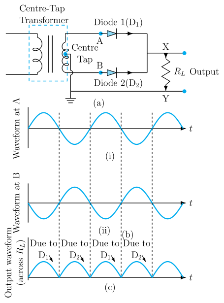
Two diodes connected to the two ends of a centre-tapped secondary winding conduct on alternate half-cycles of the AC input, but because of how they're wired, current always flows through the load resistor in the same direction — turning the bipolar sine-wave input into a unipolar (all-positive) pulsating output.
Circuit: A step-down transformer has a centre-tapped secondary winding, with its two outer ends labelled S1 (top) and S2 (bottom) and its centre tap labelled O. A diode D1 has its anode connected to S1; a diode D2 has its anode connected to S2. The cathodes of D1 and D2 are joined together at a common output point, call it P. The load resistor RL is connected between P and the centre tap O, and the rectified output voltage is taken across RL.
Working:
- During the half-cycle when S1 is positive with respect to O: D1 becomes forward biased and conducts, while S2 is negative with respect to O, so D2 is reverse biased (does not conduct). Current flows: S1 → D1 → P → through RL → back to O.
- During the next half-cycle, the polarity reverses: S2 becomes positive with respect to O, so D2 conducts (forward biased) while D1 is now reverse biased (off). Current flows: S2 → D2 → P → through RL → back to O. …
Unlock everything free for 14 days
- Full step-by-step solutions
- Concept-first explanations
- Methods, shortcuts & mistakes
- PYQ mapping + timed mock tests
Full access for 14 days. No credit card required.