Q.With the help of a diagram, explain the working of a full-wave rectifier, using a p-n junction diode. () OR Draw the forward characteristic curve of a p-n junction diode. Explain the terms depletion region and barrier potential or junction potential. (1+1+1=3)
You're viewing a preview — the full solution, concept, methods & PYQ mapping are locked.
Start your 14-day free trial to unlock the full solution →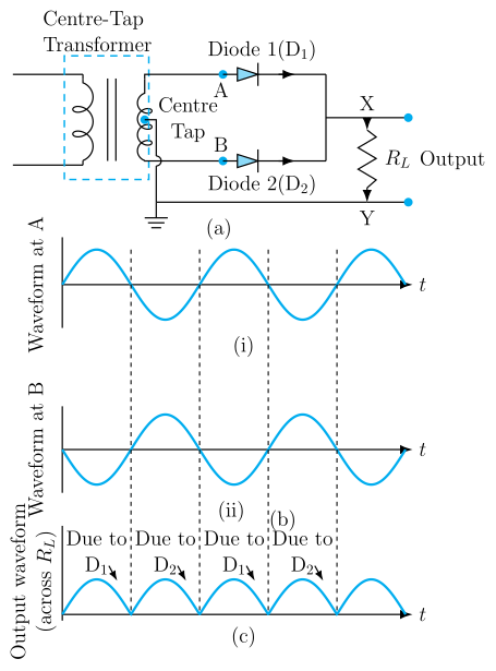
A centre-tapped full-wave rectifier uses two diodes, each conducting during alternate half-cycles of the input AC, so that current always flows through the load resistor in the same direction — giving a pulsating DC output with a pulse in every half-cycle (unlike half-wave rectification, which only conducts for half the time).
Circuit description
A full-wave rectifier using a p-n junction diode typically uses a transformer with a centre-tapped secondary winding, with the two ends of the secondary (call them and ) each connected through a diode ( from , from ) to a common output point; the load resistor is connected between this common output point and the centre tap of the transformer (which serves as the reference/ground for the output).
Working
- First half-cycle: suppose end of the secondary is at a higher (positive) potential relative to the centre tap, and end is at a lower (negative) potential. Diode (connected to ) becomes forward biased and conducts, sending current through . Diode (connected to , which is negative) is reverse biased and does not conduct.
- Second half-cycle: the polarity of the AC reverses — now is positive relative to the centre tap and is negative. Now becomes forward biased and conducts, while is reverse biased and blocks.
In both half-cycles, current is driven through the load resistor in the same direction (from the common output point, through , back to the centre tap) — because whichever diode conducts always feeds current into the same way. So although the diodes alternate which one conducts, the output current through never reverses direction and never actually falls to (and stays at) zero — it is a series of unidirectional "humps," one for each half-cycle of the input, i.e. twice as many pulses per input cycle as a half-wave rectifier (which produces only one pulse per full cycle and long gaps of zero current in between).
The output is thus a pulsating DC voltage across — unidirectional, but not smooth/steady (a capacitor filter is typically added afterwards to smooth it into a nearly steady DC).
…
Unlock everything free for 14 days
- Full step-by-step solutions
- Concept-first explanations
- Methods, shortcuts & mistakes
- PYQ mapping + timed mock tests
Full access for 14 days. No credit card required.