Full-Wave Rectifier: From Intuition to Precision
Imagine you have a tap that gives water in alternating bursts — forward, then backward, then forward again. You want a steady stream that always flows in one direction. A half-wave rectifier is like a one-way flap that only lets the forward bursts through, wasting the backward ones. A full-wave rectifier is smarter: it flips the backward bursts around so they also flow forward. Nothing is wasted.
That is the core idea. The AC voltage swings positive and negative. A full-wave rectifier takes both halves of the cycle and makes them contribute to a unidirectional (DC) output.
How It Works (The Intuition)
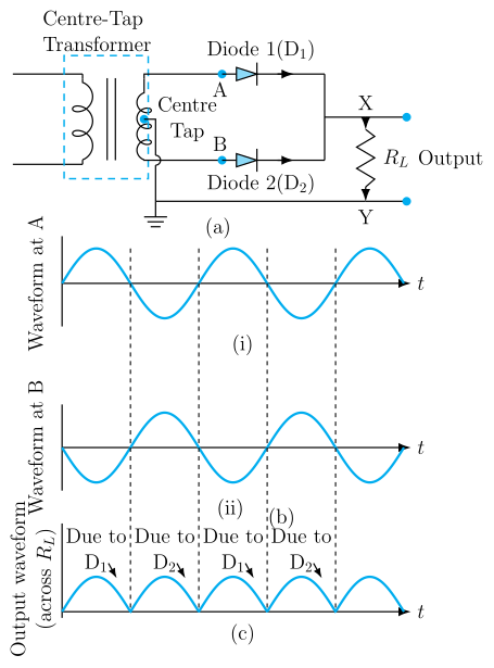
A full-wave rectifier uses either:
- Two diodes and a centre-tapped transformer, or
- Four diodes in a bridge configuration (the bridge rectifier — far more common).
In both cases, the diodes are arranged so that during the positive half-cycle, one pair conducts, and during the negative half-cycle, the other pair conducts — but the current through the load always flows the same way.
Think of the bridge rectifier as a "traffic roundabout" for current. No matter which direction the AC input pushes, the diodes steer the current so it always exits the same way through the load.
The Precise Statement
A full-wave rectifier is a circuit that converts the entire input AC waveform (both positive and negative half-cycles) into a pulsating DC output. The output voltage is always of the same polarity, and its ripple frequency is twice the input AC frequency.
For a sinusoidal input Vi=Vmsin(ωt), the output voltage (ideal diodes) is:
Vo=∣Vmsin(ωt)∣
That absolute value is the mathematical signature of full-wave rectification.
Key Result: Ripple Frequency
If the input AC has frequency f (e.g., 50 Hz), the output ripple frequency is:
fripple=2f
Why? Because each input cycle gives two output pulses — one from the positive half and one from the inverted negative half. So for 50 Hz mains, you get 100 pulses per second. This makes filtering much easier than in a half-wave rectifier (where ripple frequency equals f).
Ripple frequency = 2× input frequency. This is a direct consequence of using both halves of the AC cycle.
Average (DC) Output Voltage
For a full-wave rectifier with a sinusoidal input of peak voltage Vm, the average (DC) output voltage is:
Vdc=π2Vm
Compare this to a half-wave rectifier, where Vdc=Vm/π. The full-wave gives double the average output for the same peak input — another reason it is more efficient.
--- …