Q.Deduce the Boolean expression for the output (Y) of the following logic gate. OR Draw symbol diagram and truth table of NOR gate.
🔒You're viewing a preview — the full solution, concept, methods & PYQ mapping are locked.
🔒 Start your 14-day free trial to unlock the full solution →Concept understanding — NOR Gate
The NOR Gate: "Not OR"
Imagine you're at home with a friend. Your parent says: "I'll turn off the Wi-Fi if neither of you has finished homework." That's a NOR gate in real life. The Wi-Fi stays on (output = 1) only when both of you have finished homework (both inputs = 0). If even one person hasn't finished, the Wi-Fi goes off.
That's the core idea: NOR gives a 1 only when every single input is 0. The moment any input becomes 1, the output drops to 0.
From OR to NOR
You already know the OR gate: output is 1 if at least one input is 1. The NOR gate is simply an OR gate followed by a NOT gate (inverter). The name itself tells you: Not OR.
Y=A+B
For two inputs A and B, the truth table is:
| A | B | A + B (OR) | A+B (NOR) |
|---|---|---|---|
| 0 | 0 | 0 | 1 |
| 0 | 1 | 1 | 0 |
| 1 | 0 | 1 | 0 |
| 1 | 1 | 1 | 0 |
Notice the pattern: the NOR column is the exact opposite of the OR column. Where OR gives 1, NOR gives 0 — and vice versa.
The precise statement
A NOR gate outputs 1 only when all its inputs are 0. For any other combination of inputs, the output is 0.
For n inputs, the output is 1 if and only if every input is 0. That's the complete, exam-ready definition.
Why "universal gate"?
NOR is one of two universal gates (the other is NAND). This means you can build any logic gate — AND, OR, NOT, XOR — using only NOR gates. For example:
- NOT from NOR: connect both inputs together. Y=A+A=A
- OR from NOR: NOR followed by a NOT (which is another NOR with tied inputs). Y=A+B=A+B
- AND from NOR: use De Morgan's law: A+B=A⋅B, so A⋅B=A+B
In exam problems, if you're asked to implement a circuit using only NOR gates, remember: NOR is OR followed by NOT. To get OR back, just add another NOR as a NOT at the end.
Common mistake to avoid …
The gate shown is an AND shape with a bubble at the output = NAND gate. Its output is the inversion of the AND:
Y=A⋅B. …
The figure is a NAND gate, so Y=A⋅B.
Reading the gate. The symbol is the AND-gate body (flat back, curved front) with a small circle (inversion bubble) at the output — this is a NAND gate (NOT-AND).
Boolean expression. A NAND gives the AND of the inputs, inverted:
Y=A⋅B.
Truth table.
| A | B | A⋅B | Y=A⋅B |
|---|---|---|---|
| 0 | 0 | 0 | 1 |
| 0 | 1 | 0 | 1 |
| 1 | 0 | 0 | 1 |
- CBSE 2024Set ANNUAL1 markQ.Draw the circuit symbol of a NOR gate.
›Reveal solutionSolution
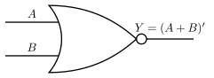
Figure — Standard 2-input NOR gate logic symbol NOR = OR + NOT, so its symbol is the OR-gate shape with an inversion bubble at the output.
The NOR gate performs the Boolean operation Y = (A + B)' — it is an OR gate followed by an inverter (NOT gate). Its standard circuit (logic) symbol is therefore built from the OR-gate symbol:
- Two inputs A and B enter from the left into a shape with a curved (concave) back and a curved, pointed front — exactly the standard OR-gate shape.
- A small circle (the 'inversion bubble') is drawn at the pointed output tip.
- The single output Y is taken from beyond this bubble. …
- CBSE 2021Set A1 markMCQQ.Boolean expression for NOR gate is (A) A + B = Y (B) ‾(A.B) = Y (C) A . B = Y (D) ‾(A + B) = Y
›Reveal solutionSolution
NOR = NOT of OR, so Y = ‾(A + B).
The OR operation is written A + B. A NOR gate inverts this output, so its Boolean expression is:
Y=A+B
…
- CBSE 2020Set ANNUAL1 markQ.Draw logic symbol of NOR gate.
›Reveal solutionSolution
A NOR gate is drawn as an OR gate symbol with a small inversion bubble (circle) at its output — it performs OR then NOT.
The standard logic symbol: two inputs A, B enter a curved-back, pointed OR-gate shape; a small circle is placed at the tip (output) of the gate to denote inversion. Boolean expression: Y=A+B.
Truth table:
A=0,B=0 → Y=1 …
- CBSE 2020Set ANNUAL1 markQ.Draw the logic symbol of NOR gate.
›Reveal solutionSolution
NOR = OR + NOT: draw the OR-gate symbol (curved-back, pointed-nose shape) with a bubble at the output; output Y=A+B.
Concept. A NOR gate gives output 1 only when all inputs are 0; it is the OR gate with its output inverted.
The logic symbol (description).
- Two input lines A and B enter the flat/curved back of an OR-gate shape.
- The body is the OR-gate shape: a concave (curved) input side tapering to a pointed output nose. …
- CBSE 2019Set ANNUAL1 markMCQQ.Figure shows the symbolic representation of (i)(OR)gate(ii) NAND gate(iii) NOR gate(iv) NOT gate
›Reveal solutionSolution
A curved-back OR-gate-shaped symbol with a small inversion bubble on its output is the standard symbol for a NOR gate.
Logic gate symbols are identified by their body shape plus the presence/absence of an output bubble:
- A curved (concave) back with a pointed front = OR-gate body (output HIGH if A OR B is HIGH).
- A flat back with a rounded/D-shaped front = AND-gate body.
- A small circle (bubble) on the output line means the output is inverted/complemented relative to the plain gate. …
- CBSE 2016Set ANNUAL1 markQ.Draw the symbol for the NOR gate.
›Reveal solutionSolution
NOR = OR gate symbol + a small inversion bubble at the output.
A NOR gate is a NOT-OR gate: it performs the OR operation on its inputs and then inverts (complements) the result, so its output is HIGH only when all inputs are LOW.
Symbol (described): it is drawn exactly like the standard 2-input OR gate — a shield-like body with a concave (curved-in) input side where the two input lines A and B enter, and a pointed, curved output side — but with a small circle ('bubble') placed at the pointed output tip. This bubble is the standard logic-symbol convention for inversion/complementation, distinguishing NOR from a plain OR gate.
…
🎓Unlock everything free for 14 days
- ✓Full step-by-step solutions
- ✓Concept-first explanations
- ✓Methods, shortcuts & mistakes
- ✓PYQ mapping + timed mock tests
Full access for 14 days. No credit card required.