Physics · Ch 9 — Mechanical Properties of Fluids
Dynamic Lift
Dynamic Lift
Dynamic Lift
When a body moves through a fluid, it experiences a force perpendicular to its motion called dynamic lift. This is not the same as the buoyant force (which acts on stationary objects) — it arises because of the motion. The most familiar examples are the upward force on an airplane wing, the sideways curve of a spinning cricket ball, and the lift on a hydrofoil.
The explanation rests squarely on Bernoulli's principle: where the fluid speed is higher, the pressure is lower. The trick is to see how the shape or spin of the body creates a difference in fluid speed on opposite sides.
Ball Moving Without Spin
Consider a smooth, non-spinning ball moving through air. The streamlines around it are perfectly symmetric — the air flows over the top and under the bottom in exactly the same way. At corresponding points above and below the ball, the air speed is identical.
Since the speeds are equal, Bernoulli's equation tells us the pressures are equal too. There is no net pressure difference, and therefore no upward or downward force. The ball follows its normal parabolic trajectory under gravity alone.
This symmetry holds only for a non-spinning ball. Even a slight roughness on the surface can disturb the symmetry, but the key point is that spin is what breaks it.
Ball Moving With Spin — The Magnus Effect
Now take a ball that is both moving forward and spinning. As it moves, it drags a layer of air along with it due to friction. If the surface is rough, more air is dragged.
Imagine a ball moving forward (say, from left to right) and spinning clockwise. Relative to the ball, the oncoming air moves backwards. On the top side of the ball, the spin drags air forward — in the same direction as the ball's motion — so the air speed relative to the ball is the sum of the ball's forward speed and the spin-induced speed. On the bottom side, the spin drags air backward, opposite to the ball's motion, so the relative air speed is the difference.
The result: air speed above the ball is larger, and below it is smaller. The streamlines crowd together above (higher speed, lower pressure) and spread out below (lower speed, higher pressure). This pressure difference produces a net upward force.
This phenomenon — dynamic lift due to spin — is called the Magnus effect. It explains why a tennis ball curves, why a cricket ball swings, and why a golf ball with backspin rises.
The Magnus effect is often oversimplified. The spin does not just "push" air; it creates a boundary layer that separates asymmetrically, and the full explanation involves the Kutta-Joukowski theorem. But for the Class 11 level, the Bernoulli-based argument is sufficient and correct.
Aerofoil — Lift on an Aircraft Wing
An aerofoil is a specially shaped solid piece designed to produce upward dynamic lift when it moves horizontally through air. The cross-section of an airplane wing is an aerofoil.
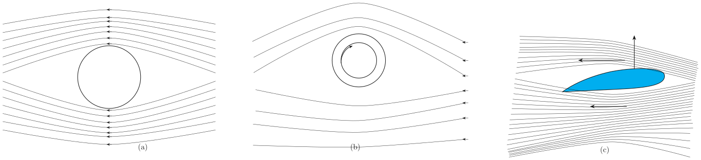
Figure 9.11(c) shows the streamlines around an aerofoil. The key is its orientation relative to the oncoming wind: the leading edge is slightly tilted upward (the angle of attack). This causes the streamlines to crowd together above the wing more than below it. …
Drawn by us to help you understand the concept clearly, and verified to make sure it's accurate. For exams, practice from your textbook's own diagram.
Fig. 9.11 is a three-panel illustration that builds the physical intuition for how a moving fluid exerts force on an object — and how that force can be turned into lift. The figure never shows a formula; it shows streamlines. But the streamlines are the visual foundation for Bernoulli’s principle applied to flow past bodies.
Panel (a) is the simplest case: a stationary sphere (drawn as a circle in cross-section) placed in a uniform fluid stream moving from left to right. The streamlines are perfectly symmetric — they part smoothly around the sphere and rejoin on the downstream side with no distortion. This symmetry tells you that the fluid speed is the same at corresponding points above and below the sphere. By Bernoulli’s equation, equal speed means equal pressure, so there is no net force perpendicular to the flow. The only force is drag, parallel to the flow, which the figure does not show.
Panel (b) introduces spin. The sphere is now rotating clockwise. The streamlines are no longer symmetric: they are crowded together above the sphere and spread apart below it. Crowded streamlines mean higher fluid speed relative to the sphere’s surface (because the rotation adds to the flow velocity on one side and subtracts on the other). Higher speed means lower pressure. So above the sphere the pressure is lower, below it the pressure is higher. The result is a net upward force — the Magnus effect. The figure shows this with a vertical arrow labelled “lift”. The same principle makes a cricket ball swing or a tennis ball curve.
Panel (c) replaces the sphere with an aerofoil — the cross-section of an airplane wing. The aerofoil is tilted slightly upward (angle of attack). The streamlines crowd together over the curved upper surface and are more widely spaced underneath. Again, crowded streamlines mean higher speed and lower pressure above; the pressure difference produces an upward lift force, shown by an arrow. The aerofoil shape is designed to keep the flow attached to the upper surface, maximising this pressure difference.
The key physical idea is that a difference in fluid speed across an object creates a pressure difference, which produces a net force perpendicular to the flow. This is the direct consequence of Bernoulli’s principle.
The central formula that the textbook develops alongside this figure is Bernoulli’s equation for steady, incompressible, non-viscous flow:
where:
- is the static pressure of the fluid at a point,
- is the density of the fluid,
- is the flow speed at that point,
- is the acceleration due to gravity,
- is the height above a reference level.
For the horizontal flows in Fig. 9.11, the term is constant, so the equation reduces to:
This is the form that directly explains the figure: wherever streamlines are crowded ( is larger), the pressure must be smaller. The pressure difference across the object — higher on the side with slower flow, lower on the side with faster flow — is what produces the lift arrow drawn in panels (b) and (c). …