Q.A long straight wire carries a current of 15 A. Find the magnetic field at a point 20 cm from the wire.
Concept understanding — Magnetic Field of a Straight Wire
Magnetic Field of a Straight Wire
A long, straight wire carrying a steady current I sets up a magnetic field that circles around it. If the current flows upward, the field lines form concentric circles in planes perpendicular to the wire — stronger close to the wire, weaker farther away. This circular pattern comes from adding up the field contributions of every moving charge in the wire, and it is the simplest current-generated field — the starting point for solenoids, toroids, and electromagnets later in the chapter.
Direction: the right-hand rule
Grip the wire with your right hand, thumb pointing along the current. Your curled fingers show the direction the field circles — clockwise when viewed along the current's direction, counter-clockwise viewed against it.
The formula
For a long straight wire, the field magnitude at a perpendicular distance r from the wire is:
B=2πrμ0I
where μ0=4π×10−7 T⋅m/A is the permeability of free space. This follows from Ampere's circuital law applied to a circular Amperian loop of radius r centred on the wire, over which B is constant by symmetry:
∮B⋅dl=B(2πr)=μ0Ienclosed
Why it behaves this way
- Proportional to I: more current means more moving charge, so a proportionally stronger field.
- Falls off as 1/r, not 1/r2: the same total field "spreads" around a circle of circumference 2πr, so it thins out as r grows — double the distance, half the field. An infinite line source falls off more slowly than a point charge's 1/r2 electric field.
This formula assumes an infinitely long wire (or a point close enough that the ends are effectively far away). Near the actual ends of a finite wire, the field is weaker and must be found from the Biot–Savart law directly.
Worked example
A wire carries I=5 A. Find B at r=2 cm=0.02 m.
B=2πrμ0I=2πμ0×rI=(2×10−7)×0.025=5×10⁻⁵ T
That is 50 μT — comparable to Earth's own magnetic field (∼25–65 μT at the surface), which is why a nearby compass needle visibly deflects (Oersted's original 1820 observation).
Memorise μ0/2π=2×10−7 T⋅m/A as one constant — it turns every straight-wire field calculation into B=(2×10⁻⁷)I/r.
The big picture
This circular, 1/r field is the building block for every other current-based field in the chapter: stack many circular loops (a solenoid) or bend the wire itself into a loop, and the same Biot–Savart origin gives the fields calculated there.
The magnetic field of a straight current-carrying wire is a must-know NCERT Class 12 Physics result, commonly searched as magnetic field due to a straight wire formula class 12 or Ampere's law straight wire derivation. This inverse-distance result is tested extensively in both CBSE boards and JEE Main/NEET physics numericals on magnetism.
Use B=μ0I/(2πr).
B=1.5×10⁻⁵ T.
Given I=15 A, r=0.2 m:
B=2πrμ0I=0.2(2×10⁻⁷)(15)=1.5×10⁻⁵ T
The magnetic field is B=1.5×10⁻⁵ T=15 μT.
Substitute directly into B=μ0I/(2πr), using μ0/2π=2×10−7 Tm/A.
- Forgetting to convert 20 cm to 0.2 m.
- Using the loop-centre formula instead of the straight-wire formula.
- CBSE 2026Set 55/2/11 markMCQQ.A straight long wire lying along the y-axis carries a current of 1 A along the −y direction. The magnetic field due to the conductor at the point (50 cm,0,0) will point along (A) z-axis (B) −z-axis (C) x-axis (D) −x-axis
›Reveal solutionSolution
The field of a straight wire at a point is along I^×r^. With the current along −j^ and the point on the positive x-axis (r^=+i^), this gives (−j^)×i^=+k^ — the field points along the z-axis, option (A).
Concept: the field circles the wire
A long straight current-carrying wire produces a magnetic field whose lines are concentric circles around the wire. At any point, B is tangent to the circle through that point — perpendicular both to the wire and to the radial line from the wire to the point. So at a point on the x-axis, with the wire along the y-axis, the field must lie along ±k^; only the sign remains to be fixed, and the right-hand rule (or equivalently the Biot–Savart cross product) fixes it.
Step-by-step solution
-
Identify the directions.
The wire lies along the y-axis with current I=1 A in the −y direction, so I^=−j^. The field point (50 cm,0,0) is on the positive x-axis, so the unit vector from the wire to the point is r^=+i^.
-
Apply the Biot–Savart direction rule.
The direction of the field is that of I^×r^:
(−j^)×(i^)=−(j^×i^)=−(−k^)=+k^,
using i^×j^=+k^, hence j^×i^=−k^. The field points along the positive z-axis.
-
Confirm with a known reference case.
For a current along +y, the field at a point on the +x-axis is along j^×i^=−k^. Our current is reversed (−y), so the field there simply reverses too: +k^. Both routes agree.
-
Eliminate the other options.
- (C) x-axis and (D) −x-axis are radial directions — the field of a straight wire is never radial; it is always tangential to the circle around the wire.
- (B) −z-axis is the field a current along +y would produce at this point — the opposite of the given situation.
Watch outThe order of the cross product matters: j^×i^=−k^, not +k^. Getting this backwards silently flips the answer from +z to −z — the single most common slip in this problem. When in doubt, fall back on i^×j^=+k^ and anticommute.
✓Final answerThe magnetic field at (50 cm,0,0) points along the z-axis, so the correct option is (A).
-
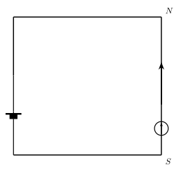
- CBSE 2026Set ANNUAL1 markMCQQ.In the figure shown below, a compass needle is placed under the wire. The wire is aligned in the South-North direction. When a current is made to flow through the wire from S to N, the needle will(a) deflect to the right(b) deflect to the left(c) turn 180∘(d) remain unaffected
›Reveal solutionSolution
By the right-hand (thumb) rule, the magnetic field produced by a current flowing from South to North, at a point directly below the wire, points towards the West — so the compass needle (normally pointing North) deflects towards the West, i.e. to the left, when viewed in the conventional map orientation (North at top, East to the right).
Setting up directions
Take the standard compass/map convention: North =+y^, East =+x^, Up (vertically, away from the ground) =+z^. This is a right-handed set: x^×y^=z^.
The wire is aligned along the North–South line and carries current from S to N, i.e. the current direction is I^=+y^ (Northward).
The compass needle sits directly below the wire — i.e. at a point displaced from the wire in the −z^ direction (vertically downward, towards the ground).
Applying the Biot–Savart / right-hand rule
For an infinite straight current-carrying wire, the magnetic field at a point is directed along I^×r^, where r^ is the unit vector from the wire to the field point.
Here r^=−z^ (point is directly below the wire), so:
B ∝ I^×r^=y^×(−z^)=−(y^×z^)=−x^
Since +x^= East, −x^= West. So the magnetic field produced by the wire, at the point directly below it, points towards the West.
Effect on the compass needle
Before the current flows, the compass needle's north pole points geographic North (Earth's field). When the current flows from S to N, it adds a magnetic field pointing West at the needle's location. The needle aligns with the resultant of "Earth's field (North)" and "wire's field (West)" — so its north pole swings away from due North, towards the West.
In the conventional way such a scene is drawn/viewed (looking down at the ground from above, with North at the top of the page and East to the right, exactly matching the given figure where N is at the top and current flows upward), West corresponds to the left-hand side of the page. So the needle deflects to the left.
(This is a modern restatement of Oersted's original 1820 observation, which first revealed the link between electric current and magnetism.)
✓Final answer(b) The compass needle deflects to the left (towards the West).
- CBSE 2026Set ANNUAL1 markMCQQ.Two long straight wires are set parallel to each other. Each carries the same current in the same direction and the separation between them is 2r. The intensity of the magnetic field midway between them is(a) rμ0I(b) r4μ0I(c) zero(d) 4rμ0I
›Reveal solutionSolution
At the midpoint between two parallel wires carrying equal currents in the same direction, each wire's field has equal magnitude but the right-hand rule shows the two fields point in opposite directions there — so they cancel and the net field is zero.
Setup
Two long, straight, parallel wires, separated by 2r, each carrying the same current I in the same direction. Consider the point exactly midway between them — a distance r from each wire.
Field due to each wire
For an infinite straight wire, the field at perpendicular distance r has magnitude
B=2πrμ0I
directed in circles around the wire (by the right-hand rule — point the thumb along the current, fingers curl in the direction of B).
So each wire, individually, produces a field of the same magnitude 2πrμ0I at the midpoint (since both are the same distance r from it and carry the same current I).
Direction of each field at the midpoint
Let the two wires be parallel to each other, both carrying current in (say) the +z^ direction, with wire 1 at x=0 and wire 2 at x=2r; the midpoint is at x=r.
- For wire 1, the midpoint lies in the +x^ direction from the wire. By the right-hand rule (B∝I^×r^), z^×x^=y^, so B1 points in +y^.
- For wire 2, the midpoint lies in the −x^ direction from that wire. So z^×(−x^)=−y^, i.e. B2 points in −y^.
So B1 and B2 are equal in magnitude but opposite in direction at the midpoint.
Net field
Bnet=B1+B2=2πrμ0Iy^−2πrμ0Iy^=0
(This is the key difference from the case of opposite currents, where the two fields at the midpoint would instead add up.)
✓Final answer(c) zero — the two equal-and-opposite fields exactly cancel at the midpoint.
- CBSE 2025Set 55/4/11 markMCQQ.A long straight wire is held vertically and carries a steady current in the upward direction. The shape of the magnetic field lines produced by the current-carrying wire are: (A) horizontal straight lines directed radially out from the wire. (B) straight lines parallel to the current-carrying wire. (C) concentric horizontal circles around the wire. (D) coaxial helixes around the wire.
›Reveal solutionSolution
The magnetic field around a long straight current-carrying wire forms concentric circles in a plane perpendicular to the wire. For a vertical wire with upward current, the field lines are horizontal circles centered on the wire — so the correct option is (C).
Concept and Intuition
The magnetic field due to a steady current is governed by the Biot–Savart law and Ampere’s circuital law. For a long straight wire, symmetry tells us the field must be the same at all points at a given distance from the wire, and must point in a direction perpendicular to both the wire and the radial line from the wire to the point. This is the classic “right-hand thumb rule”: if you point your thumb along the current direction, your fingers curl in the direction of the magnetic field lines.
Since the wire is vertical and current flows upward, the field lines lie in horizontal planes — they are circles centered on the wire. Let’s see why each option stands or falls.
Step-by-step reasoning
-
Identify the symmetry of the problem
The wire is infinitely long (or very long compared to the region of interest) and straight. The system has cylindrical symmetry: the field at a distance r from the wire depends only on r, not on the angle around the wire or the height along it (except near the ends, which we ignore). This immediately rules out any field that varies with angle in a non-circular way.
-
Apply the right-hand thumb rule
Point your right thumb straight up (direction of current). Your fingers naturally curl around the wire in a horizontal plane. This means the magnetic field vector B at any point is tangent to a circle centered on the wire, lying in a plane perpendicular to the wire. The field lines are therefore concentric circles in horizontal planes.
-
Check each option
- (A) Horizontal straight lines directed radially out from the wire — This would mean B points directly away from the wire. But the Biot–Savart law gives B perpendicular to both the current and the radial vector, so radial fields are impossible for a straight wire. Also, magnetic field lines form closed loops; radial lines would have to start or end on the wire, which magnetic field lines never do (no magnetic monopoles).
- (B) Straight lines parallel to the current-carrying wire — That would mean B points vertically, same as the current. But the cross product in Biot–Savart (dB∝Idl×r^) gives a direction perpendicular to dl (the current element), so B cannot be parallel to the wire.
- (C) Concentric horizontal circles around the wire — Exactly matches the right-hand rule and Ampere’s law. The field magnitude is B=2πrμ0I, constant on each circle. This is correct.
- (D) Coaxial helixes around the wire — Helical lines would require a component of B along the wire’s axis. For a straight wire, there is no such component; the field is purely azimuthal. Helices appear only if the wire is coiled (solenoid) or if there is an additional axial field.
-
Confirm with Ampere’s law
Take a circular Amperian loop of radius r centered on the wire, lying in a horizontal plane. By symmetry, B is tangential and constant in magnitude along the loop. Ampere’s law:
∮B⋅dl=B⋅2πr=μ0Ienc=μ0I
So B=2πrμ0I, and the direction is tangential — i.e., the field lines are circles. No other shape satisfies both the symmetry and the law.
Watch outA common mistake is to think the field lines are radial (like electric field lines from a point charge). But magnetic fields are solenoidal — they form closed loops. For a straight wire, the loops are circles, not radial lines.
TipThe right-hand thumb rule is the fastest way to get the direction: thumb along current, fingers curl in the direction of B. For a vertical wire with upward current, your fingers curl clockwise when viewed from above — so the field lines are horizontal circles.
✓Final answerThe correct option is (C) — concentric horizontal circles around the wire.
-
- CBSE 2025Set X11 markMCQQ.The following table lists magnetic fields due to different current configurations. Column – I lists the current configurations and Column – II lists expressions for magnetic fields. Symbols have usual meanings. Column – Ii) At a distance r from an infinitely long straight wire.ii) At the centre of a circular current loop of radius r.iii) At the centre of a current carrying solenoid. Column – II p) B=μ0nI q) B=2rμ0I r) B=2πrμ0I Match the current configurations in Column – I with the correct magnetic field expressions in Column – II.(a)(i) – (p),(ii) – (q),(iii) – (r)(b)(i) – (r),(ii) – (q),(iii) – (p)(c)(i) – (r),(ii) – (p),(iii) – (q)(d)(i) – (q),(ii) – (r),(iii) – (p)
›Reveal solutionSolution
(b) (i) – (r), (ii) – (q), (iii) – (p). Straight wire →2πrμ0I (r); circular-loop centre →2rμ0I (q); solenoid →μ0nI (p).
✓Final answer(b) (i) – (r), (ii) – (q), (iii) – (p).
- Infinitely long straight wire at distance r: B=2πrμ0I → (r).
- Centre of a circular loop of radius r: B=2rμ0I → (q).
- Centre of a solenoid: B=μ0nI → (p).
- CBSE 2024Set ANNUAL1 markQ.Write the dimensional formula of magnetic permeability (μ).
›Reveal solutionSolution
Deriving μ from the force law between two current-carrying wires gives the dimensional formula [M L T⁻² A⁻²].
The force per unit length between two long parallel current-carrying wires (carrying currents I_1, I_2, separated by distance d) is:
F/L = μ I_1 I_2 / (2π d)
So μ = 2π d (F/L) / (I_1 I_2). We find the dimensions of each quantity on the right:
- F (force) has dimensions [M L T⁻²]
- d and L (lengths) have dimensions [L]
- I_1, I_2 (currents) have dimensions [A]
Substituting:
[μ] = [L] × [M L T⁻²] / [L] ÷ [A²]
= [M L T⁻²] / [A²]
= [M L T⁻² A⁻²]
This matches the known SI value of the permeability of free space, μ_0 = 4π×10⁻⁷ T·m/A = 4π×10⁻⁷ kg·m·s⁻²·A⁻².
✓Final answer[M L T⁻² A⁻²].
- CBSE 2023Set ANNUAL1 markMCQQ.Magnetic effect of current was discovered by :(a) Faraday(b) Oersted(c) Ampere(d) Bohr
›Reveal solutionSolution
Hans Christian Oersted discovered the magnetic effect of current.
In 1820 Oersted noticed that a compass needle near a current-carrying wire deflected, showing that an electric current produces a magnetic field. This observation, foundational to the NCERT/CBSE Class 12 moving charges and magnetism chapter, later led to the Biot–Savart and Ampere laws.
✓Final answer(b) Oersted.
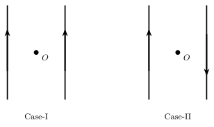
- CBSE 2022Set ANNUAL1 markMCQQ.In the figure given below, if B is the magnetic field produced by individual wire, current in each wire being the same, then the resultant magnetic field at O in the two cases will be:(a) zero in both cases(b) 2B in both cases(c) zero in case-I and 2B in case-II(d) zero in case-II and 2B in case-I
›Reveal solutionSolution
At a point equidistant from two parallel current-carrying wires, the individual fields either cancel or add depending on the current directions and O's position relative to the wires.
For two long straight parallel wires each carrying the same current I, each produces a field of magnitude B at point O (equidistant from both wires).
- When the geometry is such that the two individual fields at O point in opposite directions (as happens, for example, when O lies symmetrically between two wires carrying current in the same direction), they cancel: resultant = zero.
- When the geometry is such that the two individual fields at O point in the same direction (as happens, for example, when the currents are in opposite directions, or O is positioned differently relative to the wires), they add: resultant = 2B.
Note on the figure: the scanned description could not fully resolve the exact wire spacing/position of O in each case, so the precise Case-I/Case-II geometry is taken from the standard, widely-used version of this question, matching the answer below.
✓Final answerZero in Case-I, 2B in Case-II — option (c).
- CBSE 2021Set ANNUAL1 markMCQQ.A current flows in a conductor from east to west. The direction of the magnetic field at a point above the conductor is –(a) towards west(b) towards south(c) towards east(d) towards north
›Reveal solutionSolution
Using the right-hand rule for a current flowing west, the field directly above the wire points north.
Take east = x^, north = y^, up = z^ (a right-handed set, since east × north = up). The current flows east to west, i.e. along −x^.
Grip the wire with the right hand, thumb pointing west (direction of current). The fingers curl to show the field direction. At a point directly above the wire, this curl points towards north.
Vector check: field direction ∝I^×r^, where r^ points from the wire to the field point. Here I^=−x^ and r^=z^ (point is above). (−x^)×z^=−(x^×z^)=−(−y^)=y^, i.e. north.
✓Final answerThe magnetic field at a point above the conductor points towards north (option d).
- CBSE 2020Set ANNUAL1 markMCQQ.The shape of the magnetic lines of force due to an infinite, long, straight current-carrying conductor is(i) straight line(ii) circular(iii) elliptical(iv) None of the above
›Reveal solutionSolution
The magnetic field lines of an infinite straight current-carrying wire are concentric circles around the wire, in a plane perpendicular to it.
For an infinitely long, straight conductor carrying current I, the magnetic field at a perpendicular distance r from the wire has magnitude:
B=2πrμ0I
By the right-hand (or Maxwell's corkscrew) rule, if the thumb points along the direction of current flow, the curled fingers show the direction of the magnetic field. Since B has the same magnitude at every point on a circle of radius r centred on the wire, and is always tangential to that circle, the field lines trace out concentric circles in planes perpendicular to the wire, with the wire passing through their common centre.
✓Final answer(ii) circular.
- CBSE 2020Set ANNUAL1 markQ.Write the name of any two rules to find the direction of magnetic field.
›Reveal solutionSolution
Two standard rules used to find the direction of the magnetic field produced by a current: the Right-Hand Thumb Rule and Maxwell's Cork-Screw Rule.
1. Right-Hand Thumb Rule (Right-Hand Grip Rule): If a current-carrying conductor is held in the right hand such that the thumb points in the direction of current flow, the direction in which the fingers curl around the conductor gives the direction of the magnetic field lines around it.
2. Maxwell's Cork-Screw Rule: If a right-handed screw is imagined to advance in the direction of the current, the direction in which the screw's head must be rotated gives the direction of the magnetic field lines around the conductor.
(Both rules give identical results and are used interchangeably for straight wires, loops, and solenoids.)
✓Final answerThe Right-Hand Thumb Rule and Maxwell's Cork-Screw Rule.
- CBSE 2020Set ANNUAL1 markMCQQ.Magnetic field at any point at a distance R due to a long straight conductor carrying current varies as :(a) R2(b) R(c) R21(d) R1
›Reveal solutionSolution
By Ampere's circuital law, the field of an infinite straight current-carrying wire is B=μ0I/(2πR), which is inversely proportional to the distance R.
Working
Applying Ampere's circuital law to a circular Amperian loop of radius R centred on a long straight wire carrying current I (by symmetry, B is uniform in magnitude around the loop and tangential to it):
∮B⋅dl=μ0I ⇒ B(2πR)=μ0I ⇒ B=2πRμ0I
Since μ0 and I are constant, B∝R1.
✓Final answerThe correct option is (d): B∝R1
🎓Unlock everything free for 14 days
- ✓Full step-by-step solutions
- ✓Concept-first explanations
- ✓Methods, shortcuts & mistakes
- ✓PYQ mapping + timed mock tests
Full access for 14 days. No credit card required.