Q.Figure 6.7 shows planar loops of different shapes moving out of or into a region of a magnetic field which is directed normal to the plane of the loop away from the reader. Determine the direction of induced current in each loop using Lenz's law.
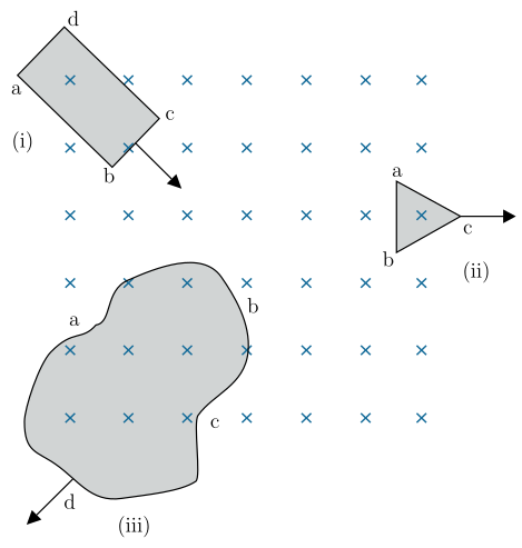
Lenz’s law says induced current opposes the change in magnetic flux. For each loop, the direction of induced current is such that its own magnetic field tries to keep the flux through the loop constant — giving clockwise or anticlockwise current as per the motion.
The core idea
Lenz’s law is a statement of energy conservation: the induced current creates a magnetic field that opposes the change in the original flux through the loop. If flux is increasing, the induced field points opposite to the original field; if flux is decreasing, the induced field points in the same direction as the original field. The direction of current is then given by the right-hand rule (curl fingers along current, thumb gives field direction).
The magnetic field in all three cases is uniform and directed into the page (the × symbols). So the original field points away from the reader, into the plane.
Step-by-step for each loop
1. Loop (i) — rectangle entering the field
The loop moves down-right, so more of its area enters the region of ×’s. The flux through the loop (into the page) is increasing.
To oppose this increase, the induced magnetic field must point out of the page (opposite to the original field). Using the right-hand rule: if the thumb points out of the page, the curled fingers show the current direction — anticlockwise (counterclockwise) as seen from above.
A quick check: when a loop enters a field, the induced current always tries to “push back” against the entering edge. Here the entering edge is the lower-right side; the induced current flows anticlockwise, which on that edge gives a force (via ) opposing the motion — consistent with Lenz.
Result for (i): Induced current flows anticlockwise (a → b → c → d → a).
2. Loop (ii) — triangle leaving the field
The triangle moves to the right, so its area inside the ×-region is decreasing. The flux into the page is decreasing.
To oppose this decrease, the induced field must point into the page (same direction as the original field). Right-hand rule: thumb into the page → fingers curl clockwise.
A common mistake: thinking that “oppose the change” means the induced field always points opposite to the original. It only does so when flux is increasing. When flux is decreasing, the induced field points with the original to try to restore it.
Result for (ii): Induced current flows clockwise (a → c → b → a, or whichever order follows the vertices).
3. Loop (iii) — irregular loop moving out
The loop moves down-left, so its area inside the ×-region is decreasing. The flux into the page is decreasing.
Same logic as (ii): decreasing flux → induced field must point into the page → current is clockwise.
The shape of the loop doesn’t matter for the direction — only the sense of flux change matters. An irregular loop behaves exactly like a circular loop for Lenz’s law.
Result for (iii): Induced current flows clockwise (a → b → c → d → a).
Summary table
| Loop | Motion | Flux change | Induced field direction | Current direction |
|---|---|---|---|---|
| (i) | Entering | Increasing | Out of page | Anticlockwise |
| (ii) | Leaving | Decreasing | Into page | Clockwise |
| (iii) | Leaving | Decreasing | Into page | Clockwise |
The induced current is anticlockwise in loop (i), clockwise in loop (ii), and clockwise in loop (iii).
Unlock everything free for 14 days
- Full step-by-step solutions
- Concept-first explanations
- Methods, shortcuts & mistakes
- PYQ mapping + timed mock tests
Full access for 14 days. No credit card required.