Physics · Ch 9 — Ray Optics and Optical Instruments
Refraction
Refraction
What is Refraction?
When light travelling in one transparent medium meets another transparent medium, part of it enters the second medium. If the light strikes the interface obliquely (at an angle between and ), its direction of propagation changes at the boundary. This bending of light as it passes from one medium to another is called refraction.
The incident ray, the refracted ray, and the normal to the interface all lie in the same plane.
Snell’s Law
The quantitative law governing refraction was discovered by Snell. It states:
The ratio of the sine of the angle of incidence () to the sine of the angle of refraction () is constant for a given pair of media.
This constant is called the refractive index of the second medium with respect to the first medium, denoted by .
- = angle between the incident ray and the normal.
- = angle between the refracted ray and the normal.
- = refractive index of medium 2 relative to medium 1.
This is Snell’s law of refraction.
Understanding the Refractive Index
- is a characteristic of the pair of media and depends on the wavelength of light, but is independent of the angle of incidence.
- If , then — the refracted ray bends towards the normal. Medium 2 is said to be optically denser than medium 1.
- If , then — the refracted ray bends away from the normal. This happens when light goes from a denser medium to a rarer medium.
Important: Optical density is not the same as mass density. It is the ratio of the speed of light in two media. For example, turpentine has a lower mass density than water but a higher optical density.
Reciprocal and Chain Rule for Refractive Indices
If is the refractive index of medium 2 with respect to medium 1, then the refractive index of medium 1 with respect to medium 2 is:
If is the refractive index of medium 3 with respect to medium 2, and is the refractive index of medium 3 with respect to medium 1, then:
Applications: Rectangular Slab and Apparent Depth
1. Rectangular Glass Slab …
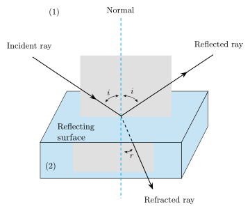
Drawn by us to help you understand the concept clearly, and verified to make sure it's accurate. For exams, practice from your NCERT textbook's own diagram.
The figure shows a horizontal interface (the boundary between two transparent media). The upper half is medium 1 (air, rarer) and the lower half is medium 2 (shaded, denser). At the point where the incident ray meets the interface, a dashed normal is drawn perpendicular to the interface.
Three rays are shown:
- Incident ray: comes from the upper left, making an angle with the normal.
- Reflected ray: goes back into medium 1 on the other side of the normal, making the same angle with the normal (law of reflection).
- Refracted ray: enters medium 2, bending toward the normal, making an angle with the normal (where because medium 2 is denser).
All three rays and the normal lie in the same plane.
Physical idea: When light passes obliquely from a rarer to a denser medium, its speed decreases, causing the ray to bend toward the normal. The figure illustrates both reflection (a part of the light returns) and refraction (the rest enters the second medium with a changed direction).
Key formula developed from this figure is Snell’s law:
where:
- = angle of incidence (between incident ray and normal)
- = angle of refraction (between refracted ray and normal) …
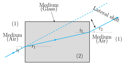
Drawn by us to help you understand the concept clearly, and verified to make sure it's accurate. For exams, practice from your NCERT textbook's own diagram.
What the diagram shows
The figure depicts a rectangular glass slab with parallel top and bottom faces, drawn as a tilted parallelogram to indicate its thickness. An incident ray approaches the top face at an angle measured from the normal (a dashed line perpendicular to the surface). Inside the glass, the ray bends toward the normal, making an angle with the normal — this is the refracted ray. It travels straight through the slab until it meets the bottom face, where it emerges into air. At the bottom interface, the ray bends away from the normal, and the angle of emergence equals the original angle of incidence . The emergent ray is therefore parallel to the incident ray but shifted sideways by a distance called the lateral shift. A dashed extension of the incident ray shows the path it would have taken if the slab were absent, making the sideways displacement visible.
Physical idea
The figure illustrates that a parallel-sided slab does not change the direction of a light ray — it only displaces it laterally. This happens because refraction at the top surface bends the ray toward the normal (since glass is optically denser than air), and refraction at the bottom surface bends it away from the normal by the same amount, restoring the original direction. The lateral shift depends on the slab thickness, the angle of incidence, and the refractive index of the glass.
Key formula
The lateral shift is given by:
where:
- = thickness of the slab,
- = angle of incidence at the top face, …
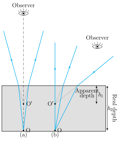
Drawn by us to help you understand the concept clearly, and verified to make sure it's accurate. For exams, practice from your NCERT textbook's own diagram.
Figure 9.10: Apparent Depth for Normal and Oblique Viewing
The figure has two side-by-side panels, both showing a vertical cross-section of a tank of water. The water is shaded, and the bottom of the tank is a horizontal line. An object O sits on the bottom. In each panel, the water surface is a horizontal line at the top of the shaded region. A normal (a dashed vertical line) is drawn at the point where a ray from O meets the surface.
Panel (a): Normal viewing
A single ray leaves O nearly vertically upward. At the water–air interface, it refracts away from the normal (since water is optically denser than air, so the ray bends away from the normal when entering the rarer medium). The actual refracted ray continues into air. A dashed line extends the refracted ray backward (into the water) until it meets the vertical line through O. This intersection point is labelled I — the apparent position of the object. The vertical distance from the water surface down to I is labelled apparent depth (), and the distance from the surface down to O is labelled real depth (). The figure shows , so the bottom appears raised.
Panel (b): Oblique viewing
Two rays leave O at different angles, both oblique (not vertical). Each ray refracts at the surface, bending away from the normal. The backward extensions of the two refracted rays (dashed lines) intersect at a point I that is shifted sideways and raised relative to O. The apparent depth is again less than the real depth, but the image is also displaced horizontally.
Physical idea
The figure teaches that when an object is viewed from a rarer medium (air) into a denser medium (water), the light rays bend away from the normal upon exiting the water. The brain interprets the rays as having travelled in straight lines, so it projects the object to a point I that is shallower than the actual object O. This is why a swimming pool or a tank of water looks shallower than it really is.
Key formula (for near-normal viewing)
For viewing nearly along the normal (small angles), the apparent depth and real depth are related by the refractive index of water (with respect to air):
where: …