Electronics · Ch 13 — Modern Communication Systems
Cellular Mobile Phone Network
Cellular Mobile Phone Network
Introduction
A cellular mobile telephone system is one that lets a user link into the ordinary (standard) telephone network and place a call to almost any part of the world, all while on the move. The cellular idea was developed in the 1970s and put into service in the early 1980s. The first systems were known as AMPS (Advanced Mobile Phone Systems) and used an analog communication technique. Analog AMPS has since been replaced by the digital 2G, 2.5G, 3G and 4G cell phone systems.
Digital cell phone systems offer three main advantages over the older analog ones:
i. the available frequency spectrum is used to the maximum through multiplexing methods, so many more users share the same band;
ii. they are more reliable in noisy environments, because digital signals resist noise better;
iii. the handsets can be made more compact while packing in more features.
The 2G digital cell phone system
Second-generation (2G) digital cell phones are built on three basic systems:
i. GSM — Global System for Mobile communication;
ii. IS-136 (an Interim Standard), also called TDMA — Time Division Multiple Access;
iii. CDMA — Code Division Multiple Access.
Architecture
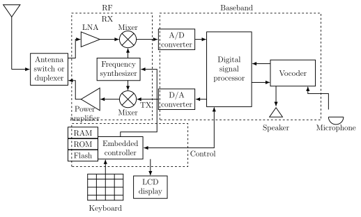
The explosive growth in cellular usage has caused spectrum crowding and interference problems. To cope with this, digital cell phones rely on digital techniques and pulse-modulation methods, and newer architectures and circuits have been developed. The overall arrangement of a basic 2G handset is shown as a block diagram in Figure 13.1.1.
Functions of various blocks
The handset is organised into three parts — an RF section, a baseband section and a control section.
- RF section: holds the transmitter and receiver circuits — the mixers, the local oscillators / frequency synthesizers used for channel selection, the receiver's low noise amplifier (LNA), and the transmitter's power amplifier.
- Baseband section: contains the vocoder together with its A/D converter and D/A converter, plus a Digital Signal Processor (DSP) chip. The DSP handles baseband and intermediate-frequency filtering, modulation, demodulation and mixing. A vocoder is a circuit that converts voice into digital form and then compresses that digital data.
- Embedded controller: manages all the digital control and signalling — hand-offs, connection and identification — carried out invisibly to the subscriber, and also runs the display, the keyboard and user functions such as number storage, autodialling and caller ID. It is usually a very fast 32-bit microprocessor with a good deal of RAM, ROM and flash memory. Extra circuitry is included to conserve power and give longer battery life.
Additional features of 3G and 4G systems
The later 3G and 4G systems add many features beyond simple voice calls, including: (i) colour LCD screens, (ii) digital cameras, (iii) e-mail, (iv) games, (v) GPS, (vi) internet access, (vii) Bluetooth, (viii) push-to-talk, (ix) voice recognition and (x) video conferencing.
Network operation and cell splitting
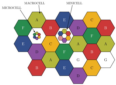
The basic idea behind a cell phone system is to divide the geographical service area into many smaller areas, a process called cell splitting. The area is divided into hexagonal cells that fit together like a honeycomb. A hexagon is chosen because it closely approximates a circle while leaving no gaps between neighbouring cells — overlapping circles would either leave gaps or waste coverage. Depending on their size, cells are further described as minicells, macrocells and microcells (see Figure 13.1.2).
Cell splitting increases the channel capacity — the number of channels available per unit area, i.e. the channel density — and decreases the cell radius. Each cell covers only a few square miles and has its own low-power transmitter and receiver serving just the users inside it. Every cell is connected by a microwave radio-relay link to a master control centre called the MTSO (Mobile Telephone Switching Office), which controls all the cells.
Frequency reuse
In frequency reuse, the individual frequency bands are shared among many base stations and users. This is arranged by grouping cells into a cluster so that one subscriber or base station does not interfere with another. Each cluster is allotted the same number of channels. Cells marked with the same letter use the same set of channel frequencies, and that same set is reused in different clusters across the pattern (illustrated in Figure 13.1.2). Reusing frequencies in this careful way is what lets a limited slice of spectrum serve a very large number of users.
Call hand-off
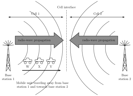
As a person carrying a cell phone moves from one cell into another, the MTSO automatically switches the ongoing call from the first cell to the next. The receiver in every cell continuously monitors the signal strength of each mobile unit, and the MTSO computer switches a call in progress from a weaker cell to a stronger one based on that signal strength. This switching is called call hand-off. It is unnoticeable to the user because it takes place in a very short time (see Figure 13.1.3).
Frequency bands
Cell phone systems work in the UHF (Ultra High Frequency) and microwave bands assigned by the FCC (Federal Communication Commission). The original allocation lay in the 800 MHz–900 MHz range:
- 824 MHz to 849 MHz — reserved for the uplink (cell phone to base station);
- 869 MHz to 894 MHz — reserved for the downlink (base station to cell phone). …
A communication system that allows a mobile user to connect into the standard (landline) telephone network and place calls anywhere in the world while on the move, by dividing the service area into small cells each s …
The technique of dividing the total geographical service area into many smaller hexagonal cells arranged in a honeycomb pattern. It increases channel capacity (channels per unit area) and reduces the cell radius, since each small cell reuses the spectrum wi …
The sharing of the same set of channel frequencies by different clusters of cells. Cells far enough apart (marked with the same letter) reuse identical frequencies without interfering, so a limited …
The automatic switching of an ongoing call by the MTSO from a weaker cell to a stronger neighbouring cell as the mobile moves, based on the signal strength each cell's receiver measures. It happens so quic …
Drawn by us to help you understand the concept clearly, and verified to make sure it's accurate. For exams, practice from your textbook's own diagram.
Reproduces textbook Figure 13.1.1 — the block diagram of a basic 2G cell phone. On the receive path the antenna feeds a duplexer, then LNA, mixer and A/D converter into the DSP and vocoder out to the speaker; on transmit the microphone feeds the vocoder, DSP, D/A converter, mixer and power amplifier back to the antenna. A central frequency synthesizer drives both mixers, and an embedded controller with RAM/ROM/flash runs the keyboard and LCD display. It matters because it shows how vo …
Drawn by us to help you understand the concept clearly, and verified to make sure it's accurate. For exams, practice from your textbook's own diagram.
Reproduces textbook Figure 13.1.2 — a honeycomb of hexagonal cells, each labelled with a letter A–G. Cells sharing the same letter use the same channel frequencies, illustrating frequency reuse, while callouts mark the smaller microcells and minicells nested among the larger macrocells. It matters because it visually explains both why hexagons are used ( …
Drawn by us to help you understand the concept clearly, and verified to make sure it's accurate. For exams, practice from your textbook's own diagram.
Reproduces textbook Figure 13.1.3 — two neighbouring cells (Cell 1 and Cell 2) with their base stations and radio-wave fronts meeting at a dashed 'cell interface'. A mobile unit is drawn at three successive positions (W, X, Y) as it moves away from base station 1 and towards base station 2, showing where the MTSO hands the call over from one cell to the other …