Electronics · Ch 13 — Modern Communication Systems
RADAR Communication System
RADAR Communication System
RADAR stands for Radio Detection And Ranging. It is a system used to detect and find the exact location of a distant object — called the target in radar terminology — or to determine the target's velocity. Radars are used extensively in both defence and civilian work: they operate day and night and in all weathers, give very broad coverage, and can produce high-resolution images. Radar is a principal navigational aid for ships, aircraft and missiles (here navigation means the process of directing an object's movement from one position to another along a desired path).
Principle of operation
A radar works by transmitting radio waves from a scanning antenna. The electromagnetic (EM) wave is sent out as a pulse. When this pulse strikes a target it is reflected, and the radar's receiver detects the reflected EM wave (the echo or return, also called scattering) to reveal the object's presence. The outgoing signal is produced by a powerful transmitter, and the faint echo is picked up by a highly sensitive receiver.
Determining the range
The range (distance) of the target is found from the time difference between the transmitted pulse and the received echo. Because the wave travels to the target and back, this time corresponds to twice the range, so:
Worked example. Suppose a signal goes to the target and returns in 1 ms. Taking the velocity of an EM wave as :
The scanning antenna also fixes the direction of the target: the direction in which the antenna is pointing at the instant the echo returns gives the direction of the target relative to the transmitter.
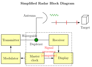
Block diagram of a radar (Figure 13.3.1)
The main blocks of a radar system and their functions are:
- Transmitter: produces the high-power RF pulses that the antenna radiates into space.
- Duplexer: switches the single antenna between the transmitter and the receiver alternately, so that the high-power transmitted pulse does not reach and destroy the sensitive receiver.
- Receiver: amplifies and demodulates the received RF echo and delivers a video signal at its output.
- Radar antenna: transfers the transmitted signal into space with the required distribution and efficiency, and is used in exactly the same way to collect the echo on reception.
- Indicator / display: presents a continuous graphic picture of the position of the radar targets to the observer.
- Modulator: a circuit that performs the mathematical multiplication of the carrier and the information signal, feeding the resulting analog signal to the transmitter.
Classification of radar systems
Radar systems are broadly classified as: …
Short for Radio Detection And Ranging — a system that transmits pulsed radio waves from a scanning antenna and detects the reflected echo to find the location, range or velocity of a distant target. It works day and night in all weather …
The target range is found from the round-trip time of the pulse, halved because the wave travels to the target and back: . For a 1 ms round trip with EM-wave speed : $ \text{Range} = \dfrac{(1\times10^{-3})(3\times1 …
Drawn by us to help you understand the concept clearly, and verified to make sure it's accurate. For exams, practice from your textbook's own diagram.
Reproduces textbook Figure 13.3.1 — the simplified radar block diagram. The modulator drives the transmitter, whose high-power pulse passes through the duplexer to the antenna and out to the target; the reflected echo returns through the antenna and duplexer to the receiver, and on to the signal processor (clocked by a master clock) and the display. It matters because it shows ho …