Physics · Ch 5 — Magnetism and Matter
Bar Magnet as an Equivalent Solenoid
Bar Magnet as an Equivalent Solenoid
The Core Idea: A Bar Magnet is Like a Solenoid
A current-carrying solenoid behaves like a magnetic dipole. The magnetic field lines of a bar magnet and a finite solenoid are strikingly similar, especially at large distances. This suggests that a bar magnet can be thought of as an equivalent solenoid — a collection of many tiny circulating currents (Ampere's hypothesis).
- If you cut a bar magnet in half, you get two smaller magnets. Similarly, cutting a solenoid in half gives two smaller solenoids with weaker fields.
- The field lines are continuous: they emerge from one face (the north pole) and enter the other face (the south pole).
- A small compass needle shows the same deflection near a bar magnet and near a current-carrying solenoid, confirming the analogy.
Deriving the Axial Field of a Solenoid
To make the analogy quantitative, we calculate the magnetic field at a point on the axis of a finite solenoid (see Fig. 5.3(a) in the textbook). At large distances ( length of solenoid), the field simplifies to a form identical to that of a bar magnet.
The result is:
Where:
- = magnitude of the magnetic field at point on the axis, far from the solenoid.
- = permeability of free space ().
- = magnetic moment of the solenoid (or the equivalent bar magnet).
- = distance from the centre of the solenoid/magnet to point .
This is exactly the far axial field of a bar magnet (obtained experimentally). Therefore, a bar magnet and a solenoid produce the same magnetic field at large distances.
Key Result: Magnetic Moment Equivalence …
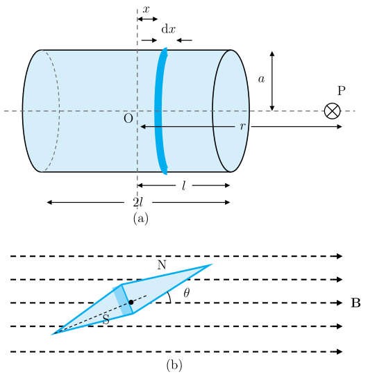
Drawn by us to help you understand the concept clearly, and verified to make sure it's accurate. For exams, practice from your textbook's own diagram.
Panel (a): Axial field of a finite solenoid
The left panel shows a finite solenoid — a cylindrical coil of wire — drawn in three dimensions. A dashed horizontal line runs through the centre of the solenoid, labelled O at the centre, and extends to a point P on the right. The solenoid has total length , with half-length marked from O to the right end. Its radius is , shown as a vertical line from the axis to the top edge of the solenoid near a thin current-element ring.
A thin shaded ring of width is highlighted at a distance from O along the axis. This ring represents a single current loop of the solenoid. The distance from O to P is labelled . At P, a symbol indicates the magnetic field points into the page (the field direction along the axis of a solenoid).
The purpose of this panel is to set up the calculation of the axial magnetic field of a finite solenoid. By treating the solenoid as a stack of circular current loops, each of magnetic moment , and integrating their contributions along the axis, one obtains the total field at P. At large distances (), the result simplifies to the far-axial field of a bar magnet:
where:
- is the permeability of free space,
- is the magnetic moment of the solenoid (or bar magnet),
- is the distance from the centre O to the point P.
This formula is equation (5.1) in the textbook. It shows that the solenoid behaves like a magnetic dipole at large distances, exactly as a bar magnet does.
Panel (b): Magnetic needle in a uniform field
The right panel shows a uniform magnetic field represented by horizontal dashed lines with rightward arrowheads. A slim magnetic needle (a small bar magnet) is placed in this field, tilted at an angle relative to the field direction. The north pole (N) is at the upper tip, the south pole (S) at the lower tip. A dashed reference line is drawn along the field direction, and the angle is marked between the needle and this line.
This panel illustrates the torque experienced by a magnetic dipole (the needle) in a uniform external field. The torque tends to align the needle with the field. The magnitude of the torque is:
where:
- is the magnetic moment of the needle,
- is the magnitude of the uniform field,
- is the angle between the needle’s axis and the field.
By measuring the deflection of the needle, one can determine either (if is known) or (if is known). This is the experimental arrangement described in the caption.