Physics · Ch 5 — Magnetism and Matter
The Magnetic Field Lines
The Magnetic Field Lines
Magnetic Field Lines: A Visual Picture of
Magnetic field lines are a way to visualize the magnetic field in space. They are not real physical lines, but a conceptual tool that helps us understand the direction and strength of the magnetic field.
How to Observe Them
- Iron filings: When sprinkled around a magnet, iron filings align themselves along the field lines, creating a visible pattern.
- Compass needle: A small magnetic compass needle, when placed at different points, will orient itself along the tangent to the field line at that point.
Key Properties of Magnetic Field Lines
-
Closed Continuous Loops: Unlike electric field lines (which start on positive charges and end on negative charges), magnetic field lines form continuous closed loops. They have no beginning or end. Inside a bar magnet, the field lines run from the south pole to the north pole, completing the loop.
-
Direction of : The tangent to a field line at any point gives the direction of the net magnetic field at that point.
-
Strength of : The density of field lines (number of lines crossing a unit area perpendicular to them) indicates the magnitude of . Where lines are crowded, the field is strong; where they are spread out, the field is weak.
-
No Intersection: Magnetic field lines never intersect. If they did, at the point of intersection there would be two different directions for , which is impossible. …
Drawn by us to help you understand the concept clearly, and verified to make sure it's accurate. For exams, practice from your textbook's own diagram.
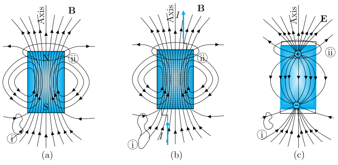
The figure presents three panels—(a), (b), and (c)—each with a vertical axis labelled “Axis” and an upward arrow at the top. The purpose is to compare the field-line patterns of a bar magnet, a finite solenoid, and an electric dipole, showing that at large distances they become nearly identical.
-
Panel (a): Bar magnet – An upright rectangular bar with N at the top and S at the bottom (letters inside the bar). Magnetic field lines emerge from the N face, arc outward down both sides, and re-enter the S face, forming closed loops. A straight line runs up through the interior from S to N. A field line at the upper-right is labelled B. Two small closed-loop Gaussian surfaces are marked: (ii) at the upper-right (enclosing the N-pole region) and (i) at the lower-left (a small loop straddling a field line).
-
Panel (b): Finite solenoid – An upright rectangle with a fine winding texture. Current I enters at the top and exits at the bottom. The external field-line pattern is the same closed-loop shape as the bar magnet. Again, B is marked at the upper-right, and Gaussian surfaces (ii) and (i) are placed similarly.
-
Panel (c): Electric dipole – An upright element with two charge regions (small circles at top and bottom). Electric field lines E run from the top charge, bulge outward to the sides, and go toward the bottom charge. These lines begin on positive charge and end on negative charge — they are not closed loops. Gaussian surfaces (ii) and (i) are again marked.
Physical idea taught:
The figure illustrates that magnetic field lines (for a bar magnet or solenoid) are continuous closed loops, unlike electric field lines of a dipole which start and end on charges. This is a fundamental difference between magnetism and electrostatics. At large distances, the external patterns of all three become indistinguishable — each behaves like a dipole field.
Key formula(s) developed with this figure:
The textbook uses this comparison to introduce the magnetic dipole moment and the magnetic field of a dipole at large distances. For a bar magnet or solenoid, the external field far away is given by:
where:
- = magnetic field at position ,
- = permeability of free space (),
- = magnetic dipole moment (for a bar magnet, points from S to N; for a solenoid, with turns, current , area , and unit vector along the axis),
- = unit vector from the dipole centre to the field point, …