Physics · Ch 11 — Magnetic Materials
Torque Acting on a Magnetic Dipole in a Uniform Magnetic Field
Torque Acting on a Magnetic Dipole in a Uniform Magnetic Field
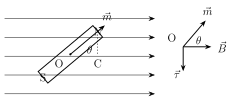
When a rectangular current-carrying coil is placed in a uniform magnetic field, it experiences a torque , of magnitude , where is the angle between the coil's magnetic moment and the field . A short bar magnet placed in a uniform field behaves in exactly the same way: the forces on its two poles, equal in magnitude but acting along different lines through the two poles, form a couple that produces a pure torque (no net translational force, since the forces on the two poles cancel exactly in a UNIFORM field) tending to rotate the magnet toward alignment with the field.
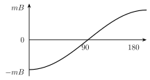
Whenever this torque produces an angular displacement, work is done on the magnet, and that work is stored as magnetic potential energy in the new orientation -- directly analogous to the electrostatic potential energy of an electric dipole in an external electric field. Integrating the torque from a reference orientation (, taken as the zero of potential energy) to a general angle gives . Three special orientations follow immediately: at (m parallel to B), and , the minimum (most negative) potential energy, so this is the magnet's most STABLE orientation; at (m antiparallel to B), and , the maximum potential energy, the most UNSTABLE orientation; and at (m perpendicular to B), and . …
Drawn by us to help you understand the concept clearly, and verified to make sure it's accurate. For exams, practice from your textbook's own diagram.
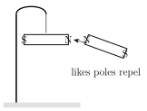
What this figure shows. A short bar magnet hangs from a fixed support by a thin, inextensible string tied around its middle, free to rotate in the horizontal plane. The magnet is shown settled along the geographic North-South direction, illustrating the everyday observation (the basis of the magnetic compass) that a freely suspended magnet always aligns itself along this direction, which the chapter uses as the starting experimental setup before perpendicular fields and torque are introd …
Drawn by us to help you understand the concept clearly, and verified to make sure it's accurate. For exams, practice from your textbook's own diagram.
What this figure shows. A bar magnet with its magnetic dipole moment vector drawn along its length (from S pole to N pole) is placed inside a uniform external magnetic field , with the two vectors making an angle between them. The forces on the two poles, equal in magnitude but acting along different parallel lines through the two poles, are shown forming a couple, whose direction is drawn as clockwise about the magnet's centre -- illustrating that a uniform field produces zero net force but a nonzero torque tending to rotat …
Drawn by us to help you understand the concept clearly, and verified to make sure it's accurate. For exams, practice from your textbook's own diagram.
What this figure shows. A graph plots the magnetic potential energy of the dipole on the vertical axis against the angle between and on the horizontal axis, following . The curve shows a minimum (most negative, most stable) value at , rises through at , and reaches a maximum (most positive, least stable) value at , visually summarising the three special cases discus …
Worked out. Starting from the freely suspended bar magnet of Fig. 11.1 (settled North-South), two related hands-on observations are suggested. First, a second short bar magnet is brought close to the freely suspended one, first presenting like poles and then unlike poles, and the student is asked to observe and conclude whether the suspended magnet rotates continuously or turns through some angle and comes to a new stable position (it settles into a new equilibrium, since a torque acts only while it is misaligned with the local resultant field). Second, without a second magnet, the suspended magnet is forcefully twisted out of its North-South rest orientation into an East-West orientation (against the restoring torque due to Earth's own horizontal field) and then released; on release it is observed to swing back and oscillate about the North-South direction before settling, which is the same restoring-torque mechanism, due here to the Earth's own field rather than a second magnet, that is anal …
Worked out. A vibration magnetometer is an instrument that uses exactly the angular-SHM result derived in this section: a small magnet is freely suspended in a uniform magnetic field and set oscillating; from its measured period of oscillation , given the magnet's known moment of inertia I, one can determine either the unknown magnetic moment m of the magnet (if B is known) or the unknown magnetic field B (if m is known) -- this is exactly the technique used in Example 11.1 to find a bar magnet's magnetic moment, and it can equally be used to deter …
Worked out. A bar magnet with moment of inertia g cm makes 10 oscillations per minute in a horizontal plane, where the horizontal component of the Earth's field is gauss. Using rearranged as , with the period s: converting units ( kg m, T) and substituting gives A m, illustrating the vibration-magnetometer technique of the preceding note applied to find an unknown magnetic moment from the o …