Physics · Ch 12 — Electromagnetic Induction
Introduction
Introduction
By the early nineteenth century, Oersted, Ampere and others had shown that an electric current produces a magnetic field around it. This chapter builds the reverse chain of reasoning that Michael Faraday (and, independently, Joseph Henry) worked out in 1831: can a changing magnetic field, or a changing magnetic flux, itself produce an electric current? Faraday's careful experiments with a magnet, a coil and a galvanometer, and later with two coils, established that it can -- this phenomenon is called electromagnetic induction, and the current it produces in a closed circuit is the induced current.
Faraday summarised his observations as follows: (i) moving a magnet's pole towards a stationary closed coil produces a current in the coil, called the induced current; (ii) withdrawing the magnet produces a current again, but in the opposite direction to (i); (iii) it is the RELATIVE motion that matters -- sliding the coil towards or away from a stationary magnet gives exactly the same effect as moving the magnet towards or away from a stationary coil; (iv) reversing the magnet's polarity reverses the direction of the induced current; (v) the size of the induced current grows with the relative speed between coil and magnet, and with the number of turns in the coil; and (vi) the induced current exists only so long as the relative motion continues -- once the magnet and coil are at rest with respect to each other, the current stops.
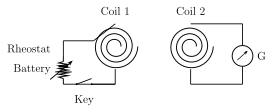
Faraday then repeated the experiment with two coils instead of a magnet and a coil: a primary coil, wired to a battery, rheostat and key, and a secondary coil, wired only to a galvanometer, with the two coils' planes facing each other. Three further observations emerged: closing or opening the primary circuit gives a momentary galvanometer kick, in opposite directions for make and break; moving either coil relative to the other (with both circuits closed) induces a current in the secondary for as long as the relative motion lasts; and simply changing the primary current's magnitude (by sliding the rheostat) -- with both coils held fixed in place -- is by itself enough to deflect the galvanometer connected to the secondary coil.
Taken together, these observations point to one single underlying cause: whenever the magnetic flux linked with a coil changes -- whether because a magnet moves, because a nearby current-carrying coil's field changes, or because the coil's own area or orientation changes -- an emf is induced in that coil, and the direction of this induced emf reverses when a growing flux turns into a shrinking one (or vice versa).
Drawn by us to help you understand the concept clearly, and verified to make sure it's accurate. For exams, practice from your textbook's own diagram.
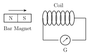
What this figure shows. Shows a bar magnet, drawn with its north pole (N) facing a stationary circular/loop coil of wire, being moved toward the coil along the coil's axis. The coil's two leads are connected to a galvanometer (G), whose needle is shown deflected, indicating that a current is flowing in the coil at the instant the magnet is approaching. The figure's sole purpose is to depict the very first of Faraday's six qualitative observations: a magnet in motion relative to a stationary closed coil induces a current in it, registered as a galvanometer deflection, with no battery or other source anywhere in the coil's own circuit.
12.1: Fig. 12.1: A bar magnet approaching a closed circuit consisting of a coil and galvanometer.
Drawn by us to help you understand the concept clearly, and verified to make sure it's accurate. For exams, practice from your textbook's own diagram.
What this figure shows. Shows two separate coils positioned coaxially with their circular planes facing one another, standing in for a magnet-and-coil pair. The coil on one side (the primary) is wired in series with a battery, a rheostat (variable resistor) and a key/switch; the coil on the other side (the secondary) is wired only to a galvanometer, with no battery of its own. The figure sets up Faraday's second experimental configuration, used to show that a current-carrying coil can play exactly the same role as a permanent magnet in inducing a current in a neighbouring coil, whether by relative motion between the two coils or simply by changing the primary's own current.
12.2: Fig. 12.2: Two coils with their planes facing each other.