Physics · Ch 1 — Rotational Dynamics
Kinematics of Circular Motion
Kinematics of Circular Motion
To describe circular motion quantitatively we use ANGULAR versions of the usual translational kinematic quantities. Angular displacement (in radians) plays the role distance/displacement s plays in translational motion; angular velocity plays the role of linear velocity ; and angular acceleration plays the role of linear acceleration . These angular quantities connect back to the familiar linear (tangential) ones through the radius vector (measured from the centre of the circular path to the particle): the tangential velocity is , with magnitude .
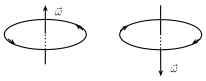
The DIRECTION of (and of ) is always along the axis of rotation -- never lying in the plane of the circle itself -- fixed by the right-hand thumb rule: curl the fingers of the right hand along the sense in which the particle is actually revolving, and the outstretched thumb then points along .
Drawn by us to help you understand the concept clearly, and verified to make sure it's accurate. For exams, practice from your textbook's own diagram.
What this figure shows. A schematic showing a particle moving along a circular path in a given plane, together with the axis of rotation drawn perpendicular to that plane through the centre of the circle. The angular velocity vector is drawn ALONG this axis (not in the plane of the circle itself), with its direction fixed by the right-hand thumb rule: if the fingers of the right hand are curled in the sense the particle is actually revolving (say anticlockwise as seen from one end of the axis), the outstretched thumb points along from that same end. The figure's purpose is purely to establish this dot/cross-free 3-D convention -- that is always perpendicular to t …
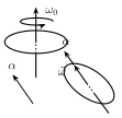
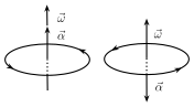
If the angular speed is INCREASING, points along the same direction as ; if the speed is DECREASING, points opposite to . As long as stays fixed along the (unchanging) axis of rotation, both and keep the same direction throughout, and we can then drop the vector notation and use plain scalar kinematics, writing the rotational analogues of the familiar ---- equations exactly as summarised in Table 1.1. (If instead had a component perpendicular to the axis, it would keep changing the DIRECTION of without changing its magnitude -- continuously tilting the plane of rotation itself -- a more complicated situation this chapter does not pursue further.)
Drawn by us to help you understand the concept clearly, and verified to make sure it's accurate. For exams, practice from your textbook's own diagram.
What this sketch shows. A loop rotating with angular velocity ω₀ about a vertical axis, and the same loop a moment later after an angular acceleration directed OFF the axis has acted: the axis itself has tilted, carrying the plane of rotation with it. As long as stays perpendicular to , only the DIRECTION of changes — not its magnitude — so th …
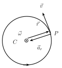
If T is the period (time for one revolution) and n is the frequency (revolutions per second), and the angular speed of a particle in UNIFORM circular motion (UCM, where the SPEED stays constant and only the direction of velocity changes) is . For UCM, the direction of stays tangential at every instant, and the resulting acceleration -- called the centripetal or radial acceleration , of constant magnitude and always pointing towards the centre -- exists purely to keep bending the velocity's direction. …
Drawn by us to help you understand the concept clearly, and verified to make sure it's accurate. For exams, practice from your textbook's own diagram.
What this figure shows. A single point on a circular trajectory (radius r from the centre) is shown with its position vector drawn from the centre outward to that point, its linear (tangential) velocity vector drawn TANGENT to the circle at that point (perpendicular to , in the sense of motion), and the centripetal/radial acceleration vector drawn pointing INWARD along , i.e. towards the centre of the circle. The figure visually establishes the mutually perpendicular triad at any instant of uniform circular motion: radially outward, tangential, and radially inward, consistent with …
Drawn by us to help you understand the concept clearly, and verified to make sure it's accurate. For exams, practice from your textbook's own diagram.
What this figure shows. A diagram similar to Fig. 1.1, showing the same axis-of-rotation convention, but now for the angular acceleration vector . It shows two cases side by side (or annotated): when the particle's speed is INCREASING, points along the SAME direction as (both arrows along the axis, same sense); when the speed is DECREASING, points OPPOSITE to (arrows along the axis but in opposite senses). No numeric values are shown; the figure exists purely to fix this sign/direction conventi …