Physics · Ch 1 — Rotational Dynamics
Linear Acceleration and Speed While Pure Rolling Down an Inclined Plane
Linear Acceleration and Speed While Pure Rolling Down an Inclined Plane
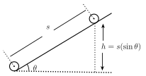
Drawn by us to help you understand the concept clearly, and verified to make sure it's accurate. For exams, practice from your textbook's own diagram.
What this figure shows. A rigid circular object (cylinder, disc or sphere) of mass M and radius R shown at the top of an inclined plane that makes angle with the horizontal, about to roll down without slipping. The object's centre is marked, with the incline's surface drawn as a straight ramp rising at angle from the horizontal ground; the object's radius R is marked from its centre to the point of contact with the incline surface. The linear distance to be travelled ALONG the incline is marked as s, related to the vertical height fallen h by (i.e. ), setting up the energy-conservation calculation of this section that relates the vertical drop h …
Consider a rigid object of mass M and radius R, with radius of gyration K, released from rest at the top of an inclined plane of angle , and allowed to roll DOWN without slipping. As it descends, its gravitational potential energy converts entirely into the kinetic energy of rolling (Eq. 1.18), since static friction (doing no net work, as there is no relative sliding at the contact point) does not dissipate any energy here. If the object falls through a vertical height h while starting from rest, energy conservation gives
The linear distance actually travelled ALONG the incline while falling through height h is (equivalently ). Since the object starts from rest () and reaches speed v (from Eq. 1.19) after travelling this distance s with some constant linear acceleration a along the incline, the ordinary kinematic relation gives (using in the last step).
For comparison, an object sliding down the SAME frictionless incline (no rotation at all) would have acceleration exactly and would reach speed exactly -- so BOTH the rolling speed and the rolling acceleration are reduced from their pure-sliding values by the identical factor . This factor depends ONLY on the ratio -- i.e. purely on the object's SHAPE -- and not at all on its mass or its actual size, which is exactly why a solid sphere, a hollow sphere, a solid cylinder and a ring, released together from the same height on the same incline, reach the bottom in a definite, mass-and-size-independent order (fastest to slowest) determined purely by their shape. …
| Equation for translational motion | Analogous equation for rotational motion |
|---|---|
| Translational motion: Quantity | Symbol/expression | Rotational motion: Quantity | Symbol/expression | Inter-relation, if possible |
|---|---|---|---|---|
| Linear displacement | Angular displacement | |||
| Linear velocity | Angular velocity | |||
| Linear acceleration | Angular acceleration | |||
| Inertia or mass | Rotational inertia or moment of inertia | |||
| Linear momentum | Angular momentum | |||
| Force | Torque | |||
| Work | Work | —— | ||
| Power | Power | —— |
| Object | Axis | Expression of moment of inertia | Figure |
|---|---|---|---|
| Thin ring or hollow cylinder | Central |  | |
| Thin ring | Diameter |  | |
| Annular ring or thick walled hollow cylinder | Central |  | |
| Uniform disc or solid cylinder | Central |  | |
| Uniform disc | Diameter |  | |
| Thin walled hollow sphere | Central |  | |
| Solid sphere | Central |  | |
| Uniform symmetric spherical shell | Central |  | |
| Thin uniform rod or rectangular plate | Perpendicular to length and passing through centre |  | |
| Thin uniform rod or rectangular plate | Perpendicular to length and about one end |  | |
| Uniform plate or rectangular parallelepiped | Central |  | |
| Uniform solid right circular cone | Central |  |