Physics · Ch 7 — Wave Optics
Refraction of Light at a Plane Boundary Between Two Media
Refraction of Light at a Plane Boundary Between Two Media
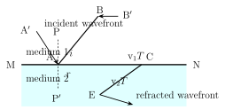
The same Huygens' wavelet construction used for reflection can be applied, with one key change, to REFRACTION -- light crossing from one medium into another with a different wave speed. Consider a wavefront AB incident on a plane boundary MN separating medium 1 (wave speed ) from medium 2 (wave speed ), at time point A has just reached the boundary while point B, further along the wavefront, only reaches it later at point C, at time , so (the distance travelled in medium 1 during the interval).
The crucial difference from the reflection case is that once point A crosses into medium 2, its secondary Huygens wavelet now grows at the NEW speed , not the original -- so by time T, this wavelet's radius is , generally different from . The REFRACTED wavefront is, exactly as before, the common tangent envelope CE to all the secondary wavelets emitted (now in medium 2) by every point between A and C during the interval to . From the right triangle ABC, ; from the right triangle AEC, (both triangles sharing hypotenuse AC). Dividing one relation by the other eliminates both T and AC entirely: , i.e. -- this is exactly Snell's Law (also called the law of refraction), now derived from wave geometry rather than simply assumed, and the construction again shows directly that the incident ray, refracted ray and the normal all lie in one plane, the other law of refraction.
This derivation makes an important physical point explicit: if (equivalently , so medium 2 is the DENSER, higher-index medium), then , i.e. -- the refracted ray bends TOWARDS the normal on entering a denser medium, and correspondingly bends AWAY from the normal when instead leaving a denser medium for a rarer one. This is precisely the correct, experimentally observed behaviour, and it follows automatically from the wave picture because light genuinely travels SLOWER in the denser medium () -- exactly the opposite of what Newton's corpuscular theory (Section 7.2.1) had wrongly predicted, and a major piece of evidence in the wave theory's favour. It is also worth noting, by contrast with reflection, that refraction does NOT produce lateral reversal, and that -- except at normal incidence, where the rays continue in the same straight-line direction with no bending at all -- an object viewed across a refracting boundary appears visually 'broken' or displaced right at the boundary, since the rays change direction abruptly on crossing it.
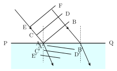
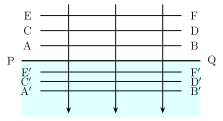
A closely related consequence of refraction concerns the WAVELENGTH of light, not just its direction. Consider light incident normally (perpendicular) on a boundary PQ between a rarer medium (speed , wavelength ) and a denser medium (speed , wavelength ). Three successive wavefronts in medium 1, each separated by exactly one wavelength , take a time to travel that spacing (since is simply the distance covered in one full period). After refraction, the SAME time elapses for the wave to cover the corresponding spacing in medium 2, so as well. Equating these two expressions for T gives -- since the denser medium has the smaller wave speed, its wavelength is correspondingly SMALLER (the wavefronts are more closely packed together there, exactly as Fig. 7.5(a)/(b) illustrate, for both normal and oblique incidence). If medium 1 is vacuum (wavelength there) and medium 2 has refractive index , this simplifies to -- the wavelength of light inside any medium is always the vacuum wavelength divided by that medium's refractive index.
Drawn by us to help you understand the concept clearly, and verified to make sure it's accurate. For exams, practice from your textbook's own diagram.
What this figure shows. The same change of wavelength shown for oblique incidence: the wavefronts AB, CD bend at the boundary (refraction) and become more closely spaced in the denser medium, confirming λ2 = λ1 n1/ …
Drawn by us to help you understand the concept clearly, and verified to make sure it's accurate. For exams, practice from your textbook's own diagram.
What this figure shows. Three successive wavefronts AB, CD, EF spaced λ1 apart in medium 1, incident normally on the boundary PQ. In the denser medium 2 the speed is smaller, so the wavefronts move slower and are closer together (spacing λ2 < λ1). The wavelength shrinks b …
…
Drawn by us to help you understand the concept clearly, and verified to make sure it's accurate. For exams, practice from your textbook's own diagram.
What this figure shows. A plane wavefront AB incident at angle i on the boundary MN between medium 1 (speed v1) and medium 2 (speed v2). While B travels BC = v1T in medium 1, the wavelet from A travels AE = v2T in medium 2; the refracted wavefront is EC. This gives …