Physics · Ch 7 — Wave Optics
Polarization
Polarization
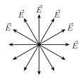
Since light is now established (Section 7.3) as a TRANSVERSE electromagnetic wave, its oscillating electric field vector at any point can, in principle, point in ANY direction within the plane perpendicular to the direction of propagation (not just along one fixed axis, unlike a wave confined to a string). Individual atoms in an ordinary light source (the Sun, a bulb) each emit their own independent light wave, and there is no reason for the electric field direction chosen by one atom's emission to match that of any other atom's -- so light from an ordinary source, viewed along its direction of travel, is a random, constantly-changing mixture of electric field oscillations in every possible direction in that perpendicular plane. Such light is called UNPOLARIZED light, conventionally represented, when viewed head-on along the propagation direction, by double-headed arrows scattered in every direction around a full circle (Fig. 7.6(a)).

Drawn by us to help you understand the concept clearly, and verified to make sure it's accurate. For exams, practice from your textbook's own diagram.
What this figure shows. Plane (linearly) polarized light coming toward us: the electric field oscillates along only ONE direction (here horizontal), drawn as a single double-headed arrow. Such light is obtained by passin …
Drawn by us to help you understand the concept clearly, and verified to make sure it's accurate. For exams, practice from your textbook's own diagram.
What this figure shows. Unpolarized light coming toward us (or going away): the electric field has components in every direction in the plane perpendicular to the direction of propagation, drawn as double-headed arrows pointing all ways. A n …
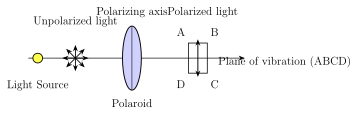
Certain materials, called POLARIZERS, have the special property of transmitting only the component of the electric field that lies along one particular fixed direction within that material, called its POLARIZING AXIS, while absorbing (blocking) the perpendicular component; a Polaroid sheet -- a synthetic plastic material engineered for exactly this selective absorption -- is the most common practical polarizer. When unpolarized light passes through a polarizer, the emergent light has its electric field confined to that one polarizing-axis direction only -- it has become PLANE POLARIZED light (Fig. 7.6(b), Fig. 7.7(a)). The plane containing both the direction of propagation and this surviving electric-field direction is called the PLANE OF VIBRATION; the plane containing the direction of propagation but PERPENDICULAR to the electric field (i.e. perpendicular to the plane of vibration) is called the PLANE OF POLARIZATION -- two complementary, mutually perpendicular planes, both containing the ray itself.
Drawn by us to help you understand the concept clearly, and verified to make sure it's accurate. For exams, practice from your textbook's own diagram.
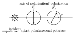
What this figure shows. Unpolarized light passes through a first polarizer (becoming plane polarized along its axis) and then a second polarizer whose axis makes an angle θ with the first. Only the component E cos θ passes the second polarizer, so the trans …
Drawn by us to help you understand the concept clearly, and verified to make sure it's accurate. For exams, practice from your textbook's own diagram.
What this figure shows. Unpolarized light from a source passes through a polaroid whose polarizing axis transmits only the field component along it; the emergent beam is plane polarized. The plane ABCD containing the transmitted electric field is the plane of vibration, and the …
Since the incident unpolarized light has its electric field spread with EQUAL likelihood over every angle from to relative to the polarizer's axis, and the intensity transmitted for any one such wave train is proportional to (the surviving component along the axis), AVERAGING over all values of from 0 to 180° gives exactly . So the intensity of unpolarized light is always reduced to exactly HALF its original value after passing through a single polarizer, REGARDLESS of how that polarizer happens to be oriented (there is no preferred direction in the incident unpolarized beam for the polarizer's axis to align with or against).
What happens next, when this now-polarized light is passed through a SECOND polarizer, is genuinely different -- and this is where the polarizer's orientation starts to matter. If the second polarizer's axis is set PERPENDICULAR to the first polarizer's axis, absolutely no light can pass through (the second polarizer only transmits field components along its own axis, and the first polarizer has already removed every component except the one now perpendicular to the second axis). If instead the second axis makes some smaller angle (less than 90°) with the first, only the COMPONENT of the already-polarized electric field along the second axis survives.
Working this out mathematically: let the wave emerging from the first polarizer have electric field , oscillating along the first polarizer's axis (call it the y-direction), with intensity (Fig. 7.7(b)). Passing through the second polarizer, whose axis makes angle with the first, only the component survives, so the emergent intensity is , i.e. -- this is MALUS' LAW, named after E. L. Malus (1775-1812) who discovered it experimentally, and it governs the intensity of already-polarized light after passing through any subsequent polarizer at angle to its current polarization direction. …