Q.What is a rectifier? Explain with a circuit diagram the working of a full-wave rectifier. (1+2=3) OR Explain with a circuit diagram, how a Zener diode can function as a voltage regulator. (1+2=3)
You're viewing a preview — the full solution, concept, methods & PYQ mapping are locked.
Start your 14-day free trial to unlock the full solution →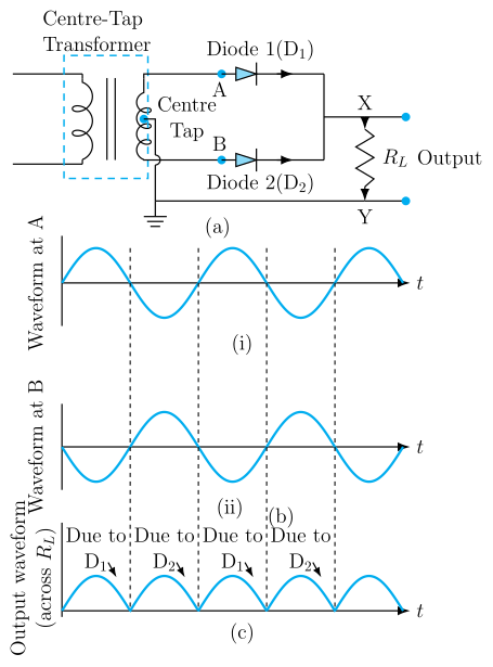
A rectifier converts AC into unidirectional (DC) current using a diode's one-way conduction; a full-wave rectifier uses two diodes (with a centre-tapped secondary) so current flows through the load during both halves of every AC cycle. In the alternative, a Zener diode reverse-biased into breakdown clamps the output at a nearly constant voltage , acting as a voltage regulator.
Rectifier
A rectifier is a circuit (built from p-n junction diode(s)) that converts alternating current/voltage into a unidirectional (pulsating direct) current/voltage, exploiting a diode's conduction only when forward biased.
Full-wave rectifier — circuit and working
A full-wave rectifier commonly uses a centre-tapped transformer secondary, the centre tap connected to one terminal of the load , and each end of the secondary connected to the anode of a diode (, ); the cathodes join and connect to the other terminal of .
During one half-cycle, the top end of the secondary is positive: is forward biased and conducts through ; is reverse biased and blocks. During the next half-cycle the polarity reverses: now conducts through (in the same direction as before, due to the centre-tapped winding), while blocks.
Current thus flows through the load in the same direction during both halves of every input cycle — the output is a series of unipolar pulses (never negative), unlike a half-wave rectifier, which conducts only during one half of each cycle.
…
Unlock everything free for 14 days
- Full step-by-step solutions
- Concept-first explanations
- Methods, shortcuts & mistakes
- PYQ mapping + timed mock tests
Full access for 14 days. No credit card required.