Physics · Ch 10 — Wave Optics
Reflection of a Plane Wave by a Plane Surface
Reflection of a Plane Wave by a Plane Surface
Reflection of a Plane Wave by a Plane Surface
When a plane wavefront strikes a flat reflecting surface, the reflected wavefront can be constructed using Huygens' principle. The goal is to find the relationship between the angle of incidence and the angle of reflection.
Step-by-step Derivation
-
Incident Wavefront: Consider a plane wavefront incident on a reflecting surface at an angle (the angle of incidence). The wavefront is perpendicular to the direction of propagation.
-
Wave Motion: Let be the speed of the wave in the medium. The wavefront advances from point to point on the surface in time . The distance travelled is:
-
Secondary Wavelet from A: At the same time, point on the incident wavefront has just touched the surface. According to Huygens' principle, point acts as a source of secondary spherical wavelets. In time , this wavelet expands to a sphere of radius centred at .
-
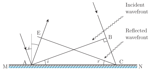
Constructing the Reflected Wavefront: To find the new position of the wavefront after time , draw a tangent plane from point to the sphere centred at . Let this tangent plane be , where is the point of tangency on the sphere. The line represents the reflected wavefront.
-
Geometric Equality: Since the radius of the sphere is , we have:
Therefore, $AE = BC = vt$.
6. Congruent Triangles: Consider triangles and :
- (both equal )
- is a common side
- (since is a radius to the tangent , and is perpendicular to the incident wavefront)
Thus, (by RHS congruence).
- Law of Reflection: From the congruence, the corresponding angles are equal:
In the diagram, $\angle EAC$ is the angle between the reflected wavefront and the surface, which equals the angle of reflection $r$. Similarly, $\angle BCA$ equals the angle of incidence $i$. Therefore:
This is the **law of reflection**.
Physical Interpretation of Wavefront Behaviour
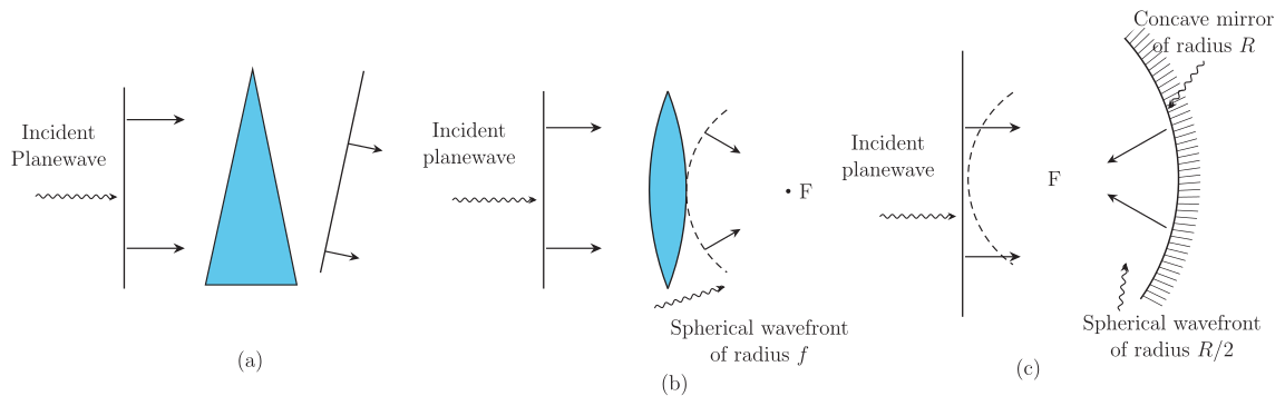
- Prisms, Lenses, and Mirrors: The laws of reflection and refraction derived from wavefront analysis explain the behaviour of optical devices. In a thin prism (Fig. 10.7a), the lower part of the wavefront travels through more glass (slower speed), causing a tilt in the emerging wavefront.
- Convex Lens (Fig. 10.7b): The central part of the incident plane wave traverses the thickest portion of the lens and is delayed the most. The emerging wavefront becomes spherical and converges to the focus . …
Drawn by us to help you understand the concept clearly, and verified to make sure it's accurate. For exams, practice from your NCERT textbook's own diagram.
The figure depicts a horizontal reflecting surface labelled . Above this surface, two wavefronts are shown: the incident wavefront and the reflected wavefront . A normal (a dashed line perpendicular to ) is drawn at the point of incidence . The angle between the incident wavefront and the surface is labelled , and the angle between the reflected wavefront and the surface is labelled . Points , , , and are marked: is on the incident wavefront, is where meets the surface, is another point on the incident wavefront, and is the point where the reflected wavefront touches the secondary wavelet from .
The physical idea is Huygens' principle applied to reflection. As the incident plane wavefront moves downward, point reaches the surface at after time , covering a distance (where is the wave speed). Meanwhile, point acts as a source of secondary wavelets; in the same time , a wavelet of radius spreads from back into the medium. The tangent line from to this wavelet gives the reflected wavefront . The geometry forces the triangles and to be congruent, leading to the law of reflection.
The key formula derived from this figure is the law of reflection:
where:
- is the angle of incidence (the angle between the incident wavefront and the reflecting surface ),
- is the angle of reflection (the angle between the reflected wavefront and the reflecting surface ). …
Drawn by us to help you understand the concept clearly, and verified to make sure it's accurate. For exams, practice from your NCERT textbook's own diagram.
What the Figure Shows
The figure has three panels, each showing a vertical plane wavefront (parallel straight lines) approaching an optical element from the left. The wavefronts are drawn as equally spaced lines representing the crests of the wave. The optical element is shown in cross-section, and the outgoing wavefronts are drawn on the right side of each element.
-
Panel (a) – Thin prism: The incoming vertical wavefront hits a triangular glass prism. The lower part of the wavefront travels through more glass (the thicker base of the prism) than the upper part. Because light slows down in glass, the lower portion is delayed more. The emerging wavefront is tilted — it is still a plane wave but now slanted relative to the incoming one. The prism is labelled, and the tilt direction shows that the wave bends toward the base of the prism.
-
Panel (b) – Convex lens: The incoming vertical plane wavefront meets a biconvex lens. The central part of the wavefront passes through the thickest part of the lens and is delayed the most. The edges pass through thinner glass and are delayed less. The emerging wavefront is curved — it has a depression at the centre, forming a spherical wave that converges to a point labelled F (the focus). The lens is labelled, and the focus is marked on the right side.
-
Panel (c) – Concave mirror: The incoming vertical plane wavefront strikes a concave mirror (curved inward). Upon reflection, the wavefront becomes spherical and converges to a point labelled F (the focus). The mirror is labelled, and the focus is shown in front of the mirror.
No axes or numerical scales are present; the figure is schematic, using wavefront lines to illustrate the change in shape and direction.
Physical Idea
The figure demonstrates how wavefronts change shape when they pass through or reflect from optical elements. The key principle is that the speed of light is slower in glass than in air (or vacuum). When a plane wave enters a medium of different thickness, different parts of the wavefront travel different distances through the slower medium, causing a time delay that distorts the wavefront.
- In the prism, the delay varies linearly across the wavefront, producing a tilt — this is the wave explanation of refraction.
- In the convex lens, the delay is greatest at the centre, so the wavefront becomes concave (depressed at the centre), which makes it converge to a point — this is how a lens focuses light.
- In the concave mirror, reflection changes the direction of propagation, and the curved surface shapes the reflected wavefront into a converging spherical one.
The figure also illustrates a deeper principle: the total time taken by light to travel from a point on the object to the corresponding point on the image is the same along any ray. For example, in the convex lens, the central ray travels a shorter path in air but spends more time in the slower glass, while the edge rays travel longer in air but less in glass — the times balance, so all rays arrive at the focus simultaneously.
Key Formula
The textbook uses this figure to develop the law of reflection and the law of refraction (Snell's law) via Huygens' principle. The relevant formula for the time delay in a medium is:
where is the speed of light in glass. For a wavefront incident at an angle, the geometry leads to Snell's law: …