Q.A 60 μF capacitor is connected to a 110 V, 60 Hz ac supply. Determine the rms value of the current in the circuit.
🔒You're viewing a preview — the full solution, concept, methods & PYQ mapping are locked.
🔒 Start your 14-day free trial to unlock the full solution →Concept understanding — Capacitive Reactance
Capacitive Reactance: The AC Resistance of a Capacitor
When you first meet a capacitor in a DC circuit, it behaves like a break in the wire once it's fully charged — no current flows. But in an AC circuit, something entirely different happens. The voltage keeps reversing, so the capacitor never finishes charging. It's constantly being filled, emptied, refilled, and re-emptied. This continuous back-and-forth means current does flow, but the capacitor resists that flow in a frequency-dependent way. That resistance is called capacitive reactance.
The Intuition: Why Frequency Matters
Imagine a water pipe with a flexible rubber membrane stretched across it (a crude capacitor). If you push water slowly from one side, the membrane bulges and eventually stops the flow — that's DC. But if you push and pull the water rapidly (AC), the membrane just vibrates, and water sloshes back and forth through the pipe. The faster you push-pull (higher frequency), the less the membrane impedes the flow. At very high frequencies, it's almost like the membrane isn't there.
In a capacitor, the "membrane" is the electric field between the plates. Higher frequency means the voltage changes faster, so the capacitor has less time to oppose the current. The result: capacitive reactance decreases as frequency increases.
The Precise Statement
Capacitive reactance XC is the opposition a capacitor offers to alternating current. It is measured in ohms (Ω), just like resistance. The formula is:
XC=2πfC1
Where:
- XC = capacitive reactance (ohms)
- f = frequency of the AC signal (hertz)
- C = capacitance (farads)
What the Formula Tells You
Three key relationships jump out:
- Inverse with frequency: Double the frequency, halve the reactance. At DC (f=0), XC becomes infinite — the capacitor blocks DC completely.
- Inverse with capacitance: A larger capacitor (more farads) offers less opposition. It can store more charge per volt, so it "gives way" more easily.
- No power dissipation: Unlike a resistor, a pure capacitor doesn't convert electrical energy to heat. Reactance is a reactive opposition — energy is stored and returned, not lost.
Do not confuse capacitive reactance with resistance. Resistance dissipates energy as heat; reactance stores and releases it. A capacitor in an AC circuit has zero real power loss (in the ideal case).
Phase: The Hidden Twist
There's a critical detail that separates reactance from resistance. In a purely resistive circuit, voltage and current peak at the same time — they are in phase. In a purely capacitive circuit, current leads voltage by 90∘ (or π/2 radians).
Why? Because current is the rate of change of charge: I=CdtdV. When the voltage is at its peak (not changing), the current is zero. When the voltage is crossing zero (changing fastest), the current is maximum. This quarter-cycle shift is baked into the definition of reactance. …
Why this formula?
Capacitive Reactance: Why XC=ωC1?
Let’s build the intuition from the ground up — starting with what a capacitor does in a circuit.
1. The Fundamental Behavior of a Capacitor
A capacitor stores charge. The defining equation is:
Q=CV
where:
- Q = charge on the plates (in coulombs)
- C = capacitance (in farads)
- V = voltage across the plates
But in an AC circuit, voltage changes continuously. So charge must also change — meaning current flows.
2. Relating Current to Voltage
Current is the rate of flow of charge:
I=dtdQ
Substitute Q=CV:
I=dtd(CV)
If C is constant (which it is for a fixed capacitor):
I=CdtdV
Key insight: The current through a capacitor is proportional to the rate of change of voltage, not the voltage itself.
3. Applying a Sinusoidal Voltage
In AC circuits, voltage is typically sinusoidal:
V(t)=V0sin(ωt)
where:
- V0 = peak voltage
- ω=2πf = angular frequency (rad/s)
Now find the current:
I(t)=Cdtd[V0sin(ωt)]=CV0⋅ωcos(ωt)
So:
I(t)=ωCV0cos(ωt)
4. The Phase Shift — Why It Matters
Notice:
- Voltage: sin(ωt)
- Current: cos(ωt)=sin(ωt+90∘)
Current leads voltage by 90∘ in a pure capacitor. This is the opposite of an inductor (where current lags).
5. Extracting the Reactance
Compare the amplitudes:
- Voltage amplitude: V0
- Current amplitude: I0=ωCV0
By Ohm’s law for AC (magnitude only):
Reactance=Current amplitudeVoltage amplitude=ωCV0V0=ωC1
Thus:
XC=ωC1=2πfC1
6. Why "Reactance" and Not "Resistance"?
- Resistance (R) dissipates energy as heat. …
The key idea is that in a purely capacitive AC circuit, the current leads the voltage by 90∘, and the rms current is given by Irms=XCVrms, where XC is the capacitive reactance.
Step 1: Compute the capacitive reactance.
XC=2πfC1=2π(60)(60×10−6)1
Step 2: Simplify the denominator.
2π×60×60×10−6=2π×3600×10−6=2π×3.6×10−3≈0.02262 …
In a purely capacitive AC circuit, the current leads the voltage by 90∘ and its rms value is given by Irms=Vrms/XC, where XC=1/(2πfC). For C=60 μF, Vrms=110 V, and f=60 Hz, the rms current is approximately 2.49 A.
Concept and Intuition
When an AC voltage is applied across a capacitor, the capacitor charges and discharges alternately. Unlike a resistor, a capacitor does not dissipate energy — it stores and returns it. But it does oppose the flow of charge, and this opposition is called capacitive reactance (XC).
The key idea: For a sinusoidal AC supply, the relationship between rms voltage and rms current in a capacitor looks just like Ohm's law — but with resistance replaced by reactance:
Irms=XCVrms,whereXC=ωC1=2πfC1
Here f is the frequency in hertz, C is the capacitance in farads. The reactance XC has units of ohms (Ω).
A common mistake is to forget converting microfarads to farads, or to use the peak voltage instead of rms. The problem directly gives rms voltage, so no conversion is needed there.
Step-by-Step Solution
1. Write down the given data
- Capacitance: C=60 μF=60×10−6 F
- RMS voltage: Vrms=110 V
- Frequency: f=60 Hz
2. Calculate the capacitive reactance
The angular frequency is ω=2πf, so:
XC=ωC1=2πfC1
Substitute the values:
XC=2π×60×60×10−61
First compute the denominator:
2π×60×60×10−6=2π×3600×10−6=2π×3.6×10−3
Using π≈3.1416:
2π×3.6×10−3≈2×3.1416×3.6×10−3=22.6195×10⁻³≈0.02262
Thus:
XC≈0.022621≈44.21 Ω …
Method: Capacitive Reactance Approach (Ohm's Law for AC Circuits)
This method treats the capacitor as a frequency-dependent resistor in an AC circuit.
Steps
- Recall the formula for capacitive reactance The opposition to current flow in a capacitor is given by:
XC=2πfC1
where f is the frequency in Hz and C is the capacitance in farads.
-
Convert units
Given: C=60 μF=60×10−6 F, Vrms=110 V, f=60 Hz.
-
Calculate XC
XC=2π(60)(60×10−6)1
XC=2π×3600×10−61
XC=2π×3.6×10−31
XC≈0.0226191≈44.21 Ω
- Apply Ohm's law for AC circuits For a purely capacitive circuit, the RMS current is: Irms=XCVrms …
Common Mistakes & How to Avoid Them
Mistake 1: Using the DC formula for power/current
The error: Students often try to use P=RV2 or I=RV, forgetting that in a pure capacitive AC circuit, there is no resistance — only capacitive reactance.
How to avoid:
- Recognise that for a pure capacitor in AC, the opposition to current is capacitive reactance XC, not resistance R.
- The correct formula is:
Irms=XCVrms
where
XC=2πfC1
Mistake 2: Forgetting to convert units
The error: Using C=60 instead of C=60×10−6 F.
How to avoid:
- Always write the unit conversion explicitly:
60 μF=60×10−6 F
- Double-check: μ means 10−6, so never plug in 60 directly.
Mistake 3: Confusing peak and rms values
The error: Using V0=110 V (peak) instead of Vrms=110 V.
How to avoid:
- The problem clearly states "110 V, 60 Hz ac supply" — in standard AC problems, this voltage is always rms unless specified as "peak" or "maximum".
- For a pure capacitor:
Irms=XCVrms
No need to convert to peak values here.
Mistake 4: Misplacing the 2π factor in XC
The error: Writing XC=2πfC or XC=fC2π.
How to avoid:
- Memorise the correct formula:
XC=2πfC1
- Think: larger f or C → smaller XC (easier for current to flow). This helps catch sign errors.
--- …
- TG EAPCET 2025Set eng-2025-05-02-AN1 markMCQQ.An inductor and a resistor are connected in series to an ac supply. If the potential differences across the inductor and the resistor are 180 V and 240 V respectively, then the voltage of the ac supply is (A) 300 V (B) 420 V (C) 60 V (D) 210 V
›Reveal solutionSolution
In a series RL circuit, the supply voltage is the phasor sum (not arithmetic sum) of the resistor and inductor voltages, so V=VR2+VL2=2402+1802=300 V.
Concept & Intuition
When an inductor and resistor are in series with an AC supply, the voltages across them are out of phase. The resistor’s voltage is in phase with the current, while the inductor’s voltage leads the current by 90∘. Because they are not aligned in time, you cannot simply add their magnitudes — you must add them as vectors (phasors) at right angles. The supply voltage is the hypotenuse of a right triangle whose legs are VR and VL.
Step-by-step reasoning
-
Identify the phase relationship
In a series RL circuit, the current I is the same through both components.
- Across the resistor: VR=IR is in phase with I.
- Across the inductor: VL=IXL leads I by 90∘. Hence VR and VL are 90∘ apart.
-
Apply phasor addition
The supply voltage V is the phasor sum of VR and VL. Since they are perpendicular, the magnitude is given by the Pythagorean theorem:
V=VR2+VL2
- Substitute the given values VR=240 V, VL=180 V V=2402+1802=57600+32400=90000 …
-
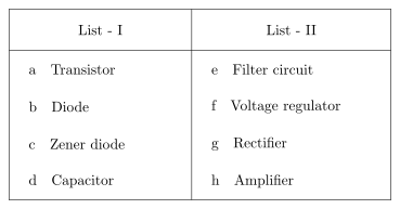
- TG EAPCET 2024Set eng-2024-05-11-FN1 markMCQQ.Match the devices given in List-I with their uses given in List-II List - I a Transistor b Diode c Zener diode d Capacitor List - II e Filter circuit f Voltage regulator g Rectifier h Amplifier The correct answer is (A) a - h, b - g, c - e, d - f (B) a - h, b - f, c - e, d - g (C) a - h, b - g, c - f, d - e (D) a - e, b - h, c - g, d - f
›Reveal solutionSolution
Transistor → amplifier, diode → rectifier, Zener → voltage regulator, capacitor → filter. That is a–h, b–g, c–f, d–e — option (C).
The concept first. All four devices show up in the same block diagram — a d.c. power supply — so it is worth seeing them in that order, because then the matching almost writes itself:
a.c. input→rectifydiode→filtercapacitor→regulateZener→steady d.c.→amplify the signaltransistor
Step 1 — Transistor (a). A transistor is a current-controlled device: a tiny base current controls a much larger collector current (IC=βIB). Biased in the active region it reproduces the input waveform at greater amplitude — an amplifier (h).
Step 2 — Diode (b). A p–n junction conducts in forward bias and blocks in reverse bias. Fed with a.c., it passes only one polarity, giving pulsating d.c. — a rectifier (g) (half-wave with one diode, full-wave with two or a bridge of four). …
- TG EAPCET 2023Set ap-2023-05-10-FN1 markMCQQ.An inductor of inductive reactance 20 Ω, a capacitor of capacitive reactance 8 Ω and a resistor of resistance 16 Ω are connected in series to an ac source of 200 V. The current through the circuit is (A) 8 A (B) 10 A (C) 16 A (D) 20 A
›Reveal solutionSolution
For a series LCR circuit, the net opposition to current is the impedance Z=R2+(XL−XC)2. Here Z=162+(20−8)2=20 Ω, so current I=V/Z=200/20=10 A. The correct option is (B).
The key idea is that in an AC series circuit, the inductor and capacitor oppose current in opposite ways — their reactances subtract, not add. The resistor always opposes current the same way. So the total opposition, called impedance, is found by combining resistance and the net reactance using the Pythagorean theorem, because the voltage across the resistor is in phase with current while the voltages across L and C are 90∘ out of phase (and opposite to each other).
-
Identify the given values
Inductive reactance XL=20 Ω
Capacitive reactance XC=8 Ω
Resistance R=16 Ω
Source voltage V=200 V (RMS)
-
Find the net reactance
Since XL and XC oppose each other, the net reactance is
X=XL−XC=20−8=12 Ω
- Calculate the impedance Impedance Z is the vector sum of resistance and net reactance: Z=R2+X2=162+122=256+144=400=20 Ω …
-
🎓Unlock everything free for 14 days
- ✓Full step-by-step solutions
- ✓Concept-first explanations
- ✓Methods, shortcuts & mistakes
- ✓PYQ mapping + timed mock tests
Full access for 14 days. No credit card required.