Q.A charged 30 μF capacitor is connected to a 27 mH inductor. What is the angular frequency of free oscillations of the circuit?
🔒You're viewing a preview — the full solution, concept, methods & PYQ mapping are locked.
🔒 Start your 14-day free trial to unlock the full solution →Concept understanding — Resonance in AC Circuits
Resonance in AC Circuits
A series circuit containing a resistor R, an inductor L and a capacitor C driven by an AC source exhibits resonance — a sharp condition at which the circuit responds most strongly.
The Competing Reactances
In a series RLC circuit the inductor and capacitor oppose the current in opposite senses. Their reactances are
XL=ωL,XC=ωC1
where ω=2πf is the angular frequency. As frequency rises, XL grows while XC shrinks. The total impedance is
Z=R2+(XL−XC)2
The Resonance Condition
At one special frequency the two reactances become exactly equal and cancel:
XL=XC⇒ω0L=ω0C1⇒ω0=LC1
The corresponding resonant frequency is
f0=2πLC1
At this frequency the impedance falls to its minimum, Z=R (purely resistive), so the current reaches its maximum value
Imax=RVrms
Because the reactances cancel, the source voltage and current are exactly in phase — the power factor is 1 at resonance.
Physical Picture
At resonance energy sloshes back and forth entirely between the inductor's magnetic field and the capacitor's electric field, cycle after cycle. The source only has to make up the small amount of energy lost as heat in R. This is the electrical analogue of a swing pushed at its natural frequency: a small periodic drive builds a large oscillation.
Sharpness and the Q-factor
How sharply the current peaks around f0 is measured by the quality factor:
Q=Rω0L=R1CL
A large Q (small R) gives a tall, narrow resonance curve — the circuit is highly selective, responding to a very narrow band of frequencies. A small Q gives a broad, flat peak.
Why It Matters …
Why this formula?
Resonance in AC Circuits: Why the Key Formulas Hold
Resonance in an AC circuit occurs when the inductive reactance (XL) and capacitive reactance (XC) exactly cancel each other out. Let's build the understanding step-by-step.
1. The Core Condition for Resonance
Consider a series RLC circuit (resistor R, inductor L, capacitor C) driven by an AC voltage source V=V0sin(ωt).
The total impedance Z of the series combination is:
Z=R+j(XL−XC)
where:
- XL=ωL (inductive reactance)
- XC=ωC1 (capacitive reactance)
- j=−1
Why resonance happens:
The circuit "wants" to let maximum current flow. The opposition to current comes from both resistance and reactance. But reactance can be negative (capacitive) or positive (inductive). When they are equal in magnitude but opposite in sign, they cancel:
XL=XC
This is the fundamental condition — not a formula to memorize, but a logical consequence of impedance minimization.
2. Deriving the Resonant Frequency
From XL=XC:
ωL=ωC1
Multiply both sides by ω:
ω2LC=1
Thus:
ω0=LC1
Since ω=2πf, the resonant frequency in hertz is:
f0=2πLC1
Why this makes sense:
- A larger L or C means the circuit takes longer to "oscillate" — lower frequency.
- A smaller L or C means faster oscillations — higher frequency.
- The product LC controls the natural time scale of the circuit.
3. What Happens at Resonance — Key Consequences
(a) Impedance is Minimum (Purely Resistive)
At resonance, XL−XC=0, so:
Z=R+j(0)=R
Why: The reactive parts cancel, leaving only the resistance. The circuit behaves like a pure resistor.
(b) Current is Maximum
From Ohm's law for AC:
I=ZV
At resonance, Z=R (minimum possible), so current is maximum:
Imax=RV
Why: The opposition to current is smallest when reactance cancels.
(c) Voltage Across L and C Can Be Very Large
The voltage across the inductor:
VL=I⋅XL=RV⋅ω0L
The voltage across the capacitor:
VC=I⋅XC=RV⋅ω0C1
Since XL=XC at resonance, VL=VC in magnitude, but they are 180° out of phase — they cancel each other in the loop.
Why this is important:
If R is small, VL and VC can be many times larger than the source voltage V. This is called voltage magnification — a key concept for tuned circuits and filters.
--- …
The key idea is that the free oscillations in an LC circuit occur at the natural resonant frequency, where energy sloshes between the capacitor and inductor.
Reasoning:
- For an ideal LC circuit (no resistance), the angular frequency of free oscillations is given by the resonance formula:
ω=LC1
-
Given values: C=30 μF=30×10−6 F, L=27 mH=27×10−3 H.
-
Substitute: …
The circuit is an ideal LC oscillator. The angular frequency of free oscillations depends only on L and C via ω=1/LC. Substituting the given values gives ω≈1.11×10³ rad/s.
The Concept: Why an LC Circuit Oscillates
When you connect a charged capacitor to an inductor, you create a perfect electrical pendulum. The capacitor stores energy in its electric field; the inductor stores energy in its magnetic field. There is no resistor here, so no energy is lost — the circuit will oscillate forever at a single natural frequency.
The key insight is that this oscillation is analogous to a mass on a spring. In a mechanical system, the angular frequency is ω=k/m where k is the spring constant and m is the mass. In an LC circuit, the inductor L plays the role of inertia (mass), and the capacitor C plays the role of stiffness (the reciprocal of the spring constant). So the natural angular frequency is:
ω=LC1
This is one of the most fundamental results in AC circuit theory. It tells you that the oscillation frequency depends only on the component values, not on how much charge you started with or what the initial voltage was.
Step-by-Step Solution
1. Identify the circuit type.
We have only a capacitor and an inductor — no resistor. This is an ideal LC circuit (also called a tank circuit). Free oscillations means the circuit is left to itself after the initial energy is supplied (here, by charging the capacitor).
2. Recall the formula for angular frequency.
For an LC circuit, the charge on the capacitor and the current in the inductor both vary sinusoidally with time. The angular frequency ω (in radians per second) is:
ω=LC1
A common mistake is to confuse angular frequency ω with ordinary frequency f. They are related by ω=2πf, but the question explicitly asks for angular frequency, so we use the formula above directly — no extra factor of 2π needed.
3. Write down the given values with correct units.
- Capacitance: C=30 μF=30×10−6 F
- Inductance: L=27 mH=27×10−3 H
Always convert micro and milli to the base SI units before plugging in.
4. Substitute into the formula.
ω=(27×10−3)(30×10−6)1
First, multiply the numbers inside the square root:
L×C=27×30×10−3×10−6=810×10−9=8.10×10⁻⁷
So: …
Method: LC Oscillation Frequency Formula (Resonance in an Ideal LC Circuit)
This method uses the fact that in a lossless LC circuit, the energy oscillates between the capacitor and inductor at a natural angular frequency determined solely by L and C.
Steps
-
Identify the given quantities
- Capacitance: C=30 μF=30×10−6 F
- Inductance: L=27 mH=27×10−3 H
-
Recall the formula for angular frequency of free oscillations
For an ideal LC circuit (no resistance), the angular frequency ω is:
ω=LC1
- Substitute the values
ω=(27×10−3)(30×10−6)1
- Simplify inside the square root
LC=27×30×10−9=810×10−9=8.1×10⁻⁷
- Take the square root …
Here are the most common mistakes students make when solving this problem, along with the conceptual fixes to avoid them.
Mistake 1: Using the wrong formula for angular frequency
The Mistake:
Students often confuse the formula for the resonant angular frequency in an LC circuit with the formula for frequency (f) or time period (T). They might write:
- ω=2πLC1 (this is actually f, not ω)
- Or they forget the square root entirely.
Why it happens:
In AC circuit theory, there are three closely related quantities: ω (angular frequency in rad/s), f (cyclic frequency in Hz), and T (time period in s). Mixing up their formulas is very common.
How to avoid it:
Memorise the exact formula for angular frequency of free oscillations in an LC circuit:
ω=LC1
- ω is in radians per second.
- If the question asks for f, then use f=2πLC1.
- Always check the unit asked in the problem — here it says angular frequency, so use ω.
Mistake 2: Forgetting to convert units to SI
The Mistake:
Plugging in values directly without converting:
- C=30 μF used as 30 instead of 30×10−6 F
- L=27 mH used as 27 instead of 27×10−3 H
Why it happens:
Micro (μ) and milli (m) prefixes are common in exam problems, but students treat them as "just numbers" out of habit.
How to avoid it:
Always write the conversion step explicitly:
C=30 μF=30×10−6 F
L=27 mH=27×10−3 H
Then substitute into the formula. This single step prevents most numerical errors.
Mistake 3: Arithmetic errors in the square root and reciprocal
The Mistake:
After substituting, students make mistakes like:
- Computing LC incorrectly (e.g., multiplying 27×30 and then handling powers of 10 wrongly)
- Taking square root incorrectly
- Forgetting to take the reciprocal at the end
How to avoid it:
Break the calculation into clear, small steps:
- Compute LC:
LC=(27×10−3)×(30×10−6)=810×10−9=8.1×10⁻⁷
- Take square root:
LC=8.1×10−7=8.1×10−3.5 (or use calculator carefully)
8.1≈2.846, and 10−3.5=10−4×100.5=10−4×10≈3.162×10⁻⁴
So LC≈2.846×3.162×10−4≈9.0×10⁻⁴ …
Showing the 12 most recent of 15 on this concept.
- TG EAPCET 2026Set eng-2026-05-09-FN1 markMCQQ.An LC circuit with negligible resistance containing a 20 mH inductor and a 50 μF capacitor with an initial charge of 10 mC is closed at t = 0. Then the minimum time taken (in μs) for the total energy to be shared equally between the inductor and capacitor is (A) 375π (B) 125π (C) 500π (D) 250π
›Reveal solutionSolution
Energy is shared equally when q=q0/2, i.e. ωt=π/4; with ω=1000 rad/s this gives t=250π μs.
In an ideal LC circuit the charge oscillates as q=q0cos(ωt), with angular frequency
ω=LC1=(20×10−3)(50×10−6)1=10−61=1000 rad/s.
The capacitor energy is UC=2Cq2 and the total energy is U=2Cq02. For the energy to be shared equally between capacitor and inductor, UC=21U:
2Cq2=21⋅2Cq02⇒q2=2q02⇒q=2q0. …
- TG EAPCET 2026Set ap-2026-05-04-FN1 markMCQQ.In the given circuit, if the potential difference between the points A and B is 90 V and the resistance of the voltmeter is 6000 Ω, then the reading of the voltmeter is (A) 40 V (B) 50 V (C) 30 V (D) 45 V
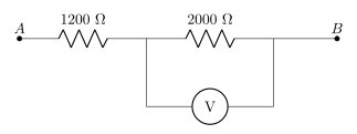
›Reveal solutionSolution
The 6000 Ω voltmeter in parallel with the 2000 Ω resistor gives 1500 Ω; with 1200 Ω in series across 90 V, the p.d. across the parallel section — which is what the meter shows — is 50 V. Option (B).
The concept: a voltmeter is part of the circuit
An ideal voltmeter has infinite resistance and draws no current, so it reports the p.d. that existed before it was connected. A real voltmeter has a large but finite resistance, so when you place it across a component:
- it forms a parallel combination with that component;
- the parallel resistance is always less than either branch, so the section's share of the total voltage drops;
- the meter faithfully reports this new, reduced p.d. — the meter is not lying, the circuit has genuinely changed. This is the loading effect, and it is why a good voltmeter is designed with resistance far larger than the resistances it is used across.
This question is designed so that the loading is deliberately noticeable (6000 Ω is only 3× the 2000 Ω resistor).
Step-by-step
- Combine the voltmeter with the resistor it is across (parallel):
Rp1=20001+60001=60003+1=60004⇒Rp=1500 Ω
- Total resistance between A and B (this parallel section is in series with the 1200 Ω resistor):
RAB=1200+1500=2700 Ω
- Current drawn from the supply: I=RABVAB=270090=301 A …
- TG EAPCET 2026Set ap-2026-05-04-FN1 markMCQQ.The quality factor of a series LCR circuit with L = 0.12 H, C = 480 nF and R = 25 Ω connected to a 220 V variable frequency supply is (A) 576 (B) 1152 (C) 60 (D) 20
›Reveal solutionSolution
The quality factor (Q) of a series LCR circuit measures the sharpness of its resonance. It is calculated using the inductance (L), capacitance (C), and resistance (R) of the circuit. For the given values, the quality factor is 20.
Concept and Intuition
A series LCR circuit consists of an inductor (L), a capacitor (C), and a resistor (R) connected in series. When an alternating current (AC) voltage is applied to such a circuit, its impedance (total opposition to current flow) varies with the frequency of the supply.
At a specific frequency, known as the resonant frequency (ω0), the inductive reactance (XL=ωL) becomes equal in magnitude to the capacitive reactance (XC=ωC1). At this point, they cancel each other out, and the circuit's impedance is purely resistive and at its minimum value (Z=R). This leads to a maximum current flow for a given voltage, a phenomenon called resonance.
The quality factor (Q) of a series LCR circuit is a dimensionless parameter that quantifies the sharpness of this resonance.
- A high Q factor indicates a very sharp and narrow resonance curve, meaning the circuit is highly selective to frequencies close to its resonant frequency. Such a circuit stores a large amount of energy compared to the energy it dissipates per cycle. This is desirable in applications like radio tuning, where you want to pick up a specific frequency very precisely.
- A low Q factor indicates a broad and flat resonance curve, meaning the circuit responds to a wider range of frequencies. It dissipates a significant amount of energy compared to what it stores.
Physically, the quality factor can be understood as the ratio of the energy stored in the circuit (in the inductor's magnetic field or capacitor's electric field) to the energy dissipated per cycle by the resistor.
The quality factor Q for a series LCR circuit is given by:
Q=Rω0L=R1CL
where ω0=LC1 is the resonant angular frequency.
The supply voltage (220 V in this case) is irrelevant for calculating the quality factor itself, as Q is an intrinsic property of the LCR components.
Step-by-step Derivation
-
Identify the given parameters:
We are given the following values for the series LCR circuit:
- Inductance, L=0.12 H
- Capacitance, C=480 nF
- Resistance, R=25 Ω
-
Convert units to SI base units: …
- TG EAPCET 2026Set ap-2026-05-04-FN1 markMCQQ.The frequency band of standard amplitude modulated broadcast is (A) 896−901 MHz (B) 88−108 MHz (C) 540−1600 kHz (D) 3.7−4.2 GHz
›Reveal solutionSolution
Standard AM broadcast uses medium-wave frequencies in the kHz range, specifically 540–1600 kHz, which corresponds to option (C).
The question asks about the frequency band for standard amplitude modulated (AM) broadcast — the kind you tune into on an AM radio. This is a factual recall point from communication systems, but it helps to understand why these frequencies are chosen.
AM broadcast works by varying the amplitude of a carrier wave to encode audio information. The carrier frequency must be high enough to carry audio (which goes up to about 5 kHz for AM) but low enough to travel long distances via ground wave propagation. Ground waves follow the Earth’s curvature and are most effective at lower frequencies — typically below a few MHz. That’s why AM broadcast uses the medium-wave (MW) band, which lies in the kHz range, not the MHz or GHz range.
Now let’s check each option:
-
Option (A): 896−901 MHz — This is in the UHF range, used for mobile phones and some TV broadcasts, not AM radio. Too high for ground wave propagation.
-
Option (B): 88−108 MHz — This is the FM broadcast band. FM uses frequency modulation, not amplitude modulation, and operates at VHF frequencies. So this is incorrect for AM. …
-
- TG EAPCET 2025Set eng-2025-05-02-AN1 markMCQQ.If L and C are inductance and capacitance respectively, then the dimensional formula of (LC)−21 is (A) [M0L0T−1] (B) [M1L1T−1] (C) [M0L1T1] (D) [M0L0T−2]
›Reveal solutionSolution
The quantity (LC)−1/2 has the dimensions of frequency (angular frequency), which is [M0L0T−1]. The correct option is (A).
The key insight is that L and C together determine the natural frequency of an LC circuit. In physics, the product LC appears in the expression for the angular frequency ω=1/LC. Since ω is a rate (radians per second), its dimension is simply inverse time. So we expect (LC)−1/2 to have dimensions [T−1].
Let’s verify this formally using dimensional analysis.
- Recall the dimensions of inductance L. Inductance is defined by V=LdtdI. Voltage V has dimensions [ML2T−3A−1] (since V=energy/charge and energy =ML2T−2, charge =AT). Current I has dimensions [A], so dI/dt has [AT−1]. Hence:
[L]=[dI/dt][V]=AT−1ML2T−3A−1=ML2T−2A−2.
- Recall the dimensions of capacitance C. Capacitance is defined by Q=CV, where charge Q has dimensions [AT]. So:
[C]=[V][Q]=ML2T−3A−1AT=M−1L−2T4A2.
- Multiply L and C.
[LC]=(ML2T−2A−2)⋅(M−1L−2T4A2)=M0L0T2A0=[T2].
Notice that all mass, length, and current dimensions cancel perfectly — leaving only time squared.
- Take the square root and then the reciprocal. …
- TG EAPCET 2024Set ap-2024-05-08-FN1 markMCQQ.A storage battery of emf 10 V and internal resistance 1 Ω is being charged by a 100 V dc supply using a series resistor of 17 Ω. The terminal voltage of the battery during charging is (A) 25 V (B) 30 V (C) 20 V (D) 15 V
›Reveal solutionSolution
The charging current is 5 A, giving a terminal voltage of 10+5(1)=15 V.
The 100V supply drives current against the battery's emf through the total resistance (series resistor + internal resistance).
Charging current:
I=R+rVsupply−ε=17+1100−10=1890=5A …
- TG EAPCET 2024Set eng-2024-05-09-FN1 markMCQQ.Three capacitors of capacitances 10μF, 5μF and 20μF are connected in series with a 14V dc supply. The charge on 5μF capacitor is (A) 20μC (B) 40μC (C) 70μC (D) 2.8μC
›Reveal solutionSolution
In a series capacitor network, each capacitor stores the same charge. The equivalent capacitance is found via the reciprocal sum, and the common charge equals that equivalent capacitance times the applied voltage. Here the charge on the 5 µF capacitor is 40 µC.
Concept & Intuition
When capacitors are connected in series to a DC source, the same amount of charge flows onto each capacitor’s plates (because the current is the same through each, and charge accumulates at the same rate). The total voltage divides inversely with capacitance. So instead of computing individual voltages, we can find the equivalent series capacitance and multiply by the total voltage — that product gives the common charge on every capacitor.
- Find the equivalent series capacitance For capacitors in series, the reciprocal of the equivalent capacitance is the sum of the reciprocals:
Ceq1=101+51+201
(all capacitances in µF). Compute:
101=0.1,51=0.2,201=0.05
Sum = 0.1+0.2+0.05=0.35.
Thus:
Ceq=0.351=35100=720μF.
- Determine the common charge The total voltage across the series combination is V=14V. The charge stored on the equivalent capacitor (and hence on each individual capacitor) is:
Q=Ceq⋅V=720μF×14V=20×2=40μC.
- Interpret the result …
- TG EAPCET 2024Set ap-2024-05-07-AN1 markMCQQ.Resonance phenomenon is exhibited by a circuit only if (A) L and R are present in the circuit (B) C and R are present in the circuit (C) R and Z are present in the circuit (D) L and C are present in the circuit
›Reveal solutionSolution
Resonance in an AC circuit requires an energy exchange between electric and magnetic fields, which demands both inductance and capacitance. The answer is (D).
Why resonance needs both L and C
Resonance is fundamentally about energy oscillation. In a mechanical system, a swing exchanges kinetic and potential energy at its natural frequency. The electrical analog requires two energy-storage elements that can trade energy back and forth:
- An inductor stores energy in its magnetic field (UL=21LI2)
- A capacitor stores energy in its electric field (UC=21CQ2)
At resonance, these two elements exchange energy at a characteristic frequency where their reactive effects cancel. The inductor's inductive reactance XL=ωL exactly balances the capacitor's capacitive reactance XC=ωC1, making the circuit behave purely resistively at that instant.
Without both elements, there is no energy exchange and no resonance frequency.
Examining each option
-
Option (A): L and R
A resistor dissipates energy as heat; it does not store it. An RL circuit has no second storage element to exchange energy with the inductor. The impedance varies with frequency, but there is no resonance peak—just a monotonic change. No resonance occurs.
-
Option (B): C and R
Similarly, an RC circuit has only one energy-storage element (the capacitor). The resistor cannot participate in energy oscillation. The impedance decreases with frequency, but again there is no resonant frequency where reactances cancel. No resonance.
-
Option (C): R and Z
This option is physically unclear. Z denotes impedance, which is a property of the entire circuit, not a component. You cannot "have impedance present" as a circuit element. This is not a meaningful statement.
-
Option (D): L and C
An LC circuit (even with resistance present) exhibits resonance. The resonance condition is: …
- TG EAPCET 2024Set ap-2024-05-07-FN1 markMCQQ.The quality factor of a series LCR resonant circuit is 75. If the resistance is decreased by 50% and the inductance is increased by 100%, then the quality factor of the circuit is (A) 150 (B) 1502 (C) 300 (D) 3002
›Reveal solutionSolution
The quality factor Q of a series LCR circuit is Q=R1CL. Changing R and L as described multiplies Q by a factor of 22, so the new Q is 75×22=1502. The correct option is (B).
Concept & Intuition
The quality factor Q measures how underdamped an RLC circuit is — essentially, how sharply it resonates. For a series LCR circuit, Q depends on resistance, inductance, and capacitance in a specific way:
Q=R1CL.
Notice that Q is inversely proportional to R and proportional to L. So if we change R and L while keeping C fixed, we can directly compute the new Q by multiplying the original by the ratio of changes. The problem gives percentage changes, which translate to simple multiplicative factors.
Step-by-step solution
- Write the original quality factor. For a series LCR circuit,
Q0=R1CL.
We are told Q0=75.
-
Interpret the changes.
- Resistance is decreased by 50%: new resistance R′=R−0.5R=0.5R.
- Inductance is increased by 100%: new inductance L′=L+1.0L=2L.
- Capacitance is not mentioned, so it remains unchanged: C′=C.
-
Write the new quality factor.
Substitute the new values into the formula:
Q′=R′1C′L′=0.5R1C2L.
- Simplify the expression.
- TG EAPCET 2024Set eng-2024-05-11-FN1 markMCQQ.For the displacement current through the plates of a parallel plate capacitor of capacitance 30μF to be 150μA, the potential difference across the plates of the capacitor has to vary at the rate of (A) 10 Vs−1 (B) 5 Vs−1 (C) 15 Vs−1 (D) 20 Vs−1
›Reveal solutionSolution
The displacement current between capacitor plates equals the conduction current in the wires, which is CdtdV. Setting CdtdV=150μA with C=30μF gives dtdV=5 V/s, so the correct option is (B).
The key idea is that displacement current is not a separate physical current — it’s the term Maxwell added to make the total current continuous in circuits with capacitors. For a parallel-plate capacitor, the displacement current between the plates exactly equals the conduction current in the connecting wires. That conduction current, in turn, is related to how fast the voltage across the capacitor changes: I=CdtdV. So the problem reduces to a simple rate calculation.
- Recall the definition of displacement current For a parallel-plate capacitor, the displacement current Id through the region between the plates is given by
Id=ε0dtdΦE,
where ΦE is the electric flux. For a uniform field between the plates, ΦE=EA, and E=V/d, so ΦE=dVA. But the capacitance is C=ε0A/d, so
Id=ε0dtd(dVA)=ε0dAdtdV=CdtdV.
This shows that the displacement current equals C times the rate of change of voltage.
- Set the displacement current equal to the given value …
- TG EAPCET 2023Set eng-2023-05-12-AN1 markMCQQ.A potentiometer balances at 44 cm when a cell of internal resistance 1 Ω is in the secondary circuit. To obtain the balancing point at 40 cm, the resistance to be connected parallel to cell is (A) 20 Ω (B) 10 Ω (C) 30 Ω (D) 5 Ω
›Reveal solutionSolution
The key idea is that the balancing length is proportional to the terminal voltage of the cell. By shunting the cell with a parallel resistor, we reduce its terminal voltage to match the new balancing length. The required parallel resistance is 10 Ω.
Concept and Intuition
In a potentiometer, the balancing length is directly proportional to the potential difference across the cell being measured (when the cell is in the secondary circuit).
If the cell has internal resistance, its terminal voltage is less than its emf when current flows. By connecting a resistor in parallel with the cell, we effectively lower the total external resistance, which changes the current drawn from the cell and thus its terminal voltage.
The problem gives two balancing lengths: one for the cell alone, and one for the cell with a parallel resistor. The ratio of these lengths equals the ratio of the corresponding terminal voltages.
Step-by-step solution
- Relate balancing length to terminal voltage For a potentiometer, the balancing length l is proportional to the potential difference across the cell’s terminals:
V∝l
So,
V1V2=l1l2
Here, l1=44 cm (cell alone), l2=40 cm (cell with parallel resistor).
- Express terminal voltages
Let the emf of the cell be E and its internal resistance r=1 Ω.
-
Case 1 (cell alone): The secondary circuit is just the cell and the potentiometer wire. The current through the cell is I1=R+rE, where R is the resistance of the potentiometer wire segment up to the balance point. But since the potentiometer draws negligible current at balance, the terminal voltage is simply E (no load). Wait — careful: In a standard potentiometer setup, the cell in the secondary circuit is not under load because the galvanometer draws no current at balance. So the terminal voltage equals the emf E.
However, the problem states the cell has internal resistance, implying that when we connect a parallel resistor, current does flow through the cell, causing a voltage drop across its internal resistance. So for the first case (no parallel resistor), the cell is essentially open-circuit, so V1=E.
-
Case 2 (with parallel resistor Rp): The cell now supplies current to the parallel resistor. The total external resistance is Rp. The current from the cell is
I2=r+RpE …
-
- TG EAPCET 2023Set ap-2023-05-11-AN1 markMCQQ.A series LCR circuit with inductance 20 mH, capacitance 50 μF and resistance 25 Ω is connected to a variable frequency supply of 220 V. The frequency of the source at which resonance occurs is (A) 1000 Hz (B) 159 Hz (C) 59 Hz (D) 50 Hz
›Reveal solutionSolution
Resonant frequency f=1/(2πLC)≈159 Hz.
Concept: At resonance in a series LCR circuit, XL=XC, so ω0=1/LC and f0=1/(2πLC). The resistance and supply voltage do not affect the resonant frequency.
Calculation:
- L=20 mH=0.02 H
- C=50 μF=50×10−6 F
- LC=0.02×50×10−6=1×10⁻⁶ s2 …
🎓Unlock everything free for 14 days
- ✓Full step-by-step solutions
- ✓Concept-first explanations
- ✓Methods, shortcuts & mistakes
- ✓PYQ mapping + timed mock tests
Full access for 14 days. No credit card required.