Q.A 44 mH inductor is connected to 220 V, 50 Hz ac supply. Determine the rms value of the current in the circuit.
Concept understanding — Inductive Reactance Change
Inductive Reactance Change – A First Look
Imagine you're pushing a child on a swing. If you push at just the right moment — when the swing is coming back toward you — each push adds energy and the swing goes higher. But if you push at random moments, sometimes you push against the swing's motion, and it barely moves. The swing "resists" being pushed at the wrong time.
An inductor in an AC circuit behaves exactly like that swing. It doesn't resist current the way a resistor does (by turning energy into heat). Instead, it resists changes in current — and the faster the current tries to change, the more the inductor pushes back.
The Core Intuition
An inductor is just a coil of wire. When current flows through it, it creates a magnetic field. If the current tries to change — say, increase or decrease — the magnetic field changes too. That changing field induces a voltage in the coil that opposes the change in current. This is Lenz's law in action: the induced voltage always fights the change that caused it.
So the inductor acts like a kind of "inertia" for current. The more rapidly the current tries to change, the stronger the opposition. In a DC circuit, once the current settles to a steady value, the inductor stops opposing — it becomes just a wire. But in an AC circuit, the current is always changing direction, so the inductor is always fighting.
The Precise Statement
Inductive reactance (XL) is the opposition an inductor offers to alternating current. It depends on two things:
- The inductance L of the coil (measured in henries, H) — bigger coil, more opposition.
- The frequency f of the AC supply (measured in hertz, Hz) — faster changes, more opposition.
The formula is:
XL=2πfL
Where:
- XL is in ohms (Ω)
- f is the frequency in Hz
- L is the inductance in H
Key point: Unlike resistance, which is constant for a given resistor, inductive reactance changes with frequency. Double the frequency, double the reactance. Halve the frequency, halve the reactance.
What "Inductive Reactance Change" Means
When we talk about "inductive reactance change," we mean: how XL varies when either the frequency or the inductance changes.
| Change | Effect on XL | Why? |
|---|---|---|
| Frequency increases | XL increases | Current changes faster → stronger opposition |
| Frequency decreases | XL decreases | Current changes slower → weaker opposition |
| Inductance increases | XL increases | More magnetic field → more opposition |
| Inductance decreases | XL decreases | Less magnetic field → less opposition |
A common mistake is to think inductive reactance behaves like resistance. It doesn't. Resistance dissipates energy as heat; reactance stores and releases energy in the magnetic field. Also, reactance depends on frequency — resistance usually doesn't.
A Simple Example
Suppose you have a coil with L=0.1 H connected to a 50 Hz AC supply.
XL=2π(50)(0.1)=2π(5)=10π≈31.4 Ω
Now change the frequency to 100 Hz:
XL=2π(100)(0.1)=2π(10)=20π≈62.8 Ω
The reactance doubled because the frequency doubled. The inductor "fights" harder at higher frequencies.
Why This Matters
In AC circuits, inductive reactance is why:
- Inductors block high-frequency signals (like in filters)
- Motors and transformers behave differently at different frequencies
- Power systems must account for reactance to avoid voltage drops
Think of XL as a "frequency-dependent resistor" — but remember, it doesn't waste power. It just stores and returns energy each cycle.
So when you hear "inductive reactance change," you now know: it's simply how the opposition of an inductor to AC varies with frequency or inductance. The formula XL=2πfL is your anchor — everything else follows from it.
Inductive reactance and how it varies with frequency, X_L = 2πfL, is a core formula from the NCERT Class 12 Physics chapter on alternating current, tested regularly in CBSE boards and JEE Main. Students searching "inductive reactance formula and frequency dependence class 12 physics" will find this frequency-versus-reactance table matches exactly what NCERT-aligned numericals expect.
Why this formula?
Inductive Reactance Change: Why the Formula Holds
Let's build this from first principles — understanding why inductive reactance behaves as it does, not just memorizing XL=2πfL.
1. The Core Idea: Opposition to Current Change
An inductor doesn't "resist" current like a resistor. Instead, it opposes changes in current due to self-induction.
- When current changes, the magnetic flux through the inductor changes.
- By Faraday's Law, a changing flux induces an emf (voltage) that opposes the change — this is Lenz's Law.
- The induced voltage is proportional to the rate of change of current:
vL=Ldtdi
Where:
- vL = induced voltage across inductor (V)
- L = inductance (henry, H)
- dtdi = rate of change of current (A/s)
2. Applying a Sinusoidal Current
In AC circuits, current is sinusoidal. Let:
i(t)=Imsin(ωt)
Where:
- Im = peak current (A)
- ω=2πf = angular frequency (rad/s)
- f = frequency (Hz)
Now compute the induced voltage:
vL=Ldtd[Imsin(ωt)]=L⋅Im⋅ωcos(ωt)
So:
vL=ωLImcos(ωt)
3. The Phase Shift: Voltage Leads Current
Notice:
- Current: sin(ωt)
- Voltage: cos(ωt)=sin(ωt+90∘)
Voltage leads current by 90∘ (or π/2 radians). This is a key property — the inductor causes a phase difference.
4. Defining Inductive Reactance
Reactance is the ratio of peak voltage to peak current (magnitude only, ignoring phase):
From above:
- Peak voltage: Vm=ωLIm
- Peak current: Im
Thus:
XL=ImVm=ωL
Since ω=2πf:
XL=2πfL
Where XL is in ohms (Ω).
5. Why It Changes with Frequency
The formula reveals the why:
- Higher frequency (f increases) → dtdi is larger for the same current amplitude → larger induced voltage → greater opposition → XL increases.
- Lower frequency (f decreases) → slower current change → smaller induced voltage → less opposition → XL decreases.
- DC (f=0) → dtdi=0 → no induced voltage → XL=0 (inductor acts as a short circuit).
6. Summary of Key Insights
| Aspect | Explanation |
|---|---|
| Origin | Faraday's Law + Lenz's Law: changing current induces opposing voltage |
| Formula | XL=2πfL |
| Frequency dependence | XL∝f — higher frequency, more opposition |
| Phase | Voltage leads current by 90∘ |
| DC behavior | XL=0 at f=0 (steady current) |
7. Exam-Relevant Takeaway
Inductive reactance is not a resistance — it's a frequency-dependent opposition arising from electromagnetic induction. The formula XL=2πfL is a direct consequence of vL=Ldtdi applied to sinusoidal signals.
Always remember: the inductor opposes change, and the faster the change (higher f), the stronger the opposition.
The key idea is that in a purely inductive AC circuit, the current lags the voltage by 90∘ and the opposition to current is given by inductive reactance XL, not resistance.
Step 1: Compute the inductive reactance.
XL=2πfL=2π×50×44×10−3
XL=2π×2.2≈13.82 Ω
Step 2: Apply Ohm's law for an AC circuit. For a pure inductor, the rms current is the rms voltage divided by the inductive reactance.
Irms=XLVrms=13.82220
Step 3: Calculate the result.
Irms≈15.92 A
The rms value of the current is 15.92 A.
For a pure inductor in an AC circuit, the current lags the voltage by 90∘ and its rms value is given by Irms=Vrms/XL, where XL=2πfL. Here, Irms≈15.9 A.
Why This Works — The Concept
When you connect an inductor to an AC supply, something interesting happens. Unlike a resistor, an inductor doesn't just "resist" current — it opposes changes in current. This opposition is called inductive reactance (XL), and it depends on both the frequency of the supply and the inductance itself.
The key idea: For a pure inductor (no resistance), the voltage and current are out of phase by exactly 90∘, with the current lagging behind the voltage. But for calculating the magnitude of the current (the rms value), we can treat the inductor just like a resistor — using Ohm's law for AC circuits:
Irms=XLVrms
where XL=2πfL is the inductive reactance in ohms.
The beauty is that rms values follow the same arithmetic as DC values, as long as we use the correct "resistance" (reactance) for the component.
Step-by-Step Solution
1. Identify the given quantities
We have:
- Inductance, L=44 mH=44×10−3 H
- Supply voltage (rms), Vrms=220 V
- Frequency, f=50 Hz
A common mistake is forgetting to convert millihenries to henries. 44 mH is 0.044 H, not 44 H!
2. Calculate the inductive reactance
The inductive reactance tells us how much the inductor "resists" the AC current:
XL=2πfL
Substitute the values:
XL=2π×50×44×10−3
XL=2π×50×0.044
XL=2π×2.2
XL=4.4π Ω
If you want a numerical value: XL≈4.4×3.1416≈13.82 Ω
3. Apply Ohm's law for AC circuits
For a pure inductor, the rms current is simply:
Irms=XLVrms
Irms=4.4π220
Simplify: 220/4.4=50, so:
Irms=π50 A
4. Get the numerical value
Irms=3.141650≈15.92 A
Notice that 50/π is an exact expression. In many exam problems, leaving the answer in terms of π is perfectly acceptable — and often preferred. The numerical approximation is 15.9 A.
Why No Phase Angle in the Answer?
You might wonder: shouldn't we account for the 90∘ phase difference? The answer is no — because the question specifically asks for the rms value of the current. RMS values are magnitudes only; they don't carry phase information. The phase angle matters when you're combining components or calculating instantaneous power, but for a single inductor's current magnitude, it's just Vrms/XL.
In a purely inductive circuit, the current lags voltage by 90∘, but the rms magnitude follows Irms=Vrms/XL — exactly like Ohm's law.
The rms value of the current is π50 A≈15.9 A.
Method: Inductive Reactance & Ohm’s Law for AC Circuits
This method uses the concept that an ideal inductor opposes AC current through inductive reactance (XL), which behaves like resistance in Ohm’s law for AC circuits.
Steps
Step 1: Recall the formula for inductive reactance
XL=2πfL
where:
- f = frequency in Hz
- L = inductance in henry (H)
Step 2: Convert units and substitute values
Given:
- L=44 mH=44×10−3 H
- f=50 Hz
- Vrms=220 V
XL=2π(50)(44×10−3)
XL=2π(2.2)
XL=4.4π Ω
Step 3: Apply Ohm’s law for AC circuits
For a purely inductive circuit:
Irms=XLVrms
Irms=4.4π220
Irms=π50
Step 4: Compute the numerical value
Irms=3.141650≈15.92 A
Final Answer
Irms≈15.92 A
Key Concept Check
- The inductor does not dissipate power (ideal case) — it only stores and returns energy.
- The current lags the voltage by 90∘ in a pure inductor.
- The opposition is reactance (XL), not resistance — hence no power dissipation, only reactive power.
Here are the common mistakes students make when solving this exact problem, along with how to avoid each one.
Mistake 1: Forgetting to Convert Inductance to Henry
The mistake:
Students see 44 mH and plug in 44 directly into the formula, forgetting the milli prefix.
Why it happens:
The formula XL=2πfL expects L in henry (H), not millihenry.
How to avoid:
Always write the conversion step explicitly:
L=44 mH=44×10−3 H=0.044 H
Mistake 2: Using the Wrong Formula for Impedance
The mistake:
Students treat the inductor like a resistor and write I=V/R, using R instead of XL.
Why it happens:
They confuse resistive circuits with inductive AC circuits.
How to avoid:
Remember: For a pure inductor, there is no resistance — only inductive reactance:
XL=2πfL
Then use Ohm’s law for AC:
Irms=XLVrms
Mistake 3: Using Peak Voltage Instead of RMS Voltage
The mistake:
Students take 220 V as peak voltage and use V0 in the formula.
Why it happens:
They forget that the problem explicitly says "220 V, 50 Hz ac supply" — this is the rms value by convention in Indian exams.
How to avoid:
In AC circuit problems, unless stated as "peak voltage" or "V0", assume the given voltage is rms.
Here:
Vrms=220 V
Mistake 4: Forgetting the Factor of 2π in XL
The mistake:
Students write XL=fL or XL=πfL, missing the 2.
Why it happens:
They memorise the formula incorrectly.
How to avoid:
Write the full formula every time:
XL=2πfL
And remember: π≈3.14, so 2π≈6.28.
Mistake 5: Calculation Errors with π
The mistake:
Using π=3.14 but making arithmetic mistakes, or rounding too early.
How to avoid:
Do the calculation step-by-step:
- XL=2×3.14×50×0.044
- First: 2×50=100
- Then: 100×0.044=4.4
- Finally: 4.4×3.14=13.816 Ω
Then:
Irms=13.816220≈15.92 A
Final answer: 15.92 A (or approximately 16 A)
Quick Checklist to Avoid All Mistakes
- Convert mH → H (×10−3)
- Use XL=2πfL, not R
- Use Vrms=220 V (not peak)
- Include 2π, not just π or fL
- Do arithmetic carefully, avoid early rounding
Master these, and you’ll never lose marks on this problem again.
Showing the 12 most recent of 16 on this concept.
- TG EAPCET 2026Set eng-2026-05-10-AN1 markMCQQ.If the energy stored in an inductor is 18mJ when a current of 3A is passed through it, then the magnetic flux linked with the inductor is (A) 36mWb (B) 24mWb (C) 18mWb (D) 12mWb
›Reveal solutionSolution
The energy stored in an inductor is U=21LI2, and the magnetic flux linkage is Φ=LI. Combining these gives Φ=I2U, which yields 12mWb.
The key idea is that the energy stored in an inductor is directly related to both its inductance and the current, while the magnetic flux linkage is the product of inductance and current. By eliminating the inductance, we can find the flux directly from the given energy and current.
- Recall the two fundamental formulas for an inductor The energy stored in an inductor is
U=21LI2,
and the magnetic flux linked (often called flux linkage) is
Φ=LI.
Here, L is the inductance, I is the current, U is the energy, and Φ is the flux linkage.
- We want Φ, but we don’t know L directly However, we can express L from the energy formula:
L=I22U.
Then substitute this into the flux formula:
Φ=LI=(I22U)I=I2U.
- Plug in the given values U=18mJ=18×10−3J and I=3A.
Φ=32×18×10−3=336×10−3=12×10−3Wb=12mWb.
TipNotice that the units work out: energy in joules (J) divided by current in amperes (A) gives webers (Wb), since 1J/A=1Wb.
Watch outA common mistake is to use U=21ΦI directly without derivation, but then forget the factor of 2. Always check: Φ=2U/I, not U/I.
✓Final answerThe correct option is (D).
ANSWER: D
- TG EAPCET 2026Set eng-2026-05-11-AN1 markMCQQ.When an inductor and a resistor are connected in series to an ac source, the power factor of the circuit is 132. If the same resistor and a capacitor are connected in series to the same ac source, then the power factor of the circuit is 21. If these inductor, capacitor and resistor are connected in series to the same ac source, then the ratio of the resistance and impedance of the LCR circuit is (A) 1:7 (B) 2:5 (C) 2:7 (D) 1:5
›Reveal solutionSolution
The power factor in an RL or RC circuit gives the ratio of resistance to impedance; combining these yields the resistance and net reactance in the LCR circuit, leading to the ratio R:Z=2:7, which corresponds to option (C).
Concept & Intuition
The power factor of an AC circuit is defined as cosϕ=ZR, where R is the resistance and Z is the impedance. For a series RL circuit, Z=R2+XL2; for a series RC circuit, Z=R2+XC2. Given the power factors, we can find the ratios XL/R and XC/R. Then, for the series LCR circuit, the net reactance is ∣XL−XC∣, and the impedance is Z=R2+(XL−XC)2. The problem asks for R:Z, which we can compute directly from these ratios.
Step-by-step solution
- RL circuit power factor Given cosϕRL=132. For RL: cosϕ=R2+XL2R=132. Square both sides:
R2+XL2R2=134
Cross-multiply:
13R2=4R2+4XL2⇒9R2=4XL2
So XL2=49R2 and thus XL=23R (taking positive reactance).
- RC circuit power factor Given cosϕRC=21. For RC: cosϕ=R2+XC2R=21. Square:
R2+XC2R2=21
Cross-multiply:
2R2=R2+XC2⇒XC2=R2
So XC=R (taking positive capacitive reactance).
- LCR series circuit The net reactance is ∣XL−XC∣=23R−R=21R. The impedance is:
Z=R2+(2R)2=R2+4R2=45R2=2R5
Therefore, the ratio of resistance to impedance is:
ZR=2R5R=52
So R:Z=2:5.
- Check the options Option (B) is 2:5. But wait — the problem asks for the ratio of resistance and impedance of the LCR circuit. That is exactly R:Z=2:5. However, let’s double-check: the power factor of the LCR circuit would be ZR=52, which is not directly given, but we computed it. So the correct option is (B).
Watch outA common mistake is to confuse the ratio R:Z with the power factor itself — they are the same thing! Here the power factor of the LCR circuit is 52, so the ratio is 2:5. Option (C) 2:7 would arise if one mistakenly used XL+XC instead of ∣XL−XC∣.
TipNotice that the power factors given for RL and RC circuits directly give the tangent of the phase angle: tanϕRL=XL/R=3/2 and tanϕRC=XC/R=1. Then for LCR, net tanϕ=∣3/2−1∣=1/2, so cosϕ=1+(1/2)21=52, confirming the ratio.
✓Final answerThe correct option is (B).
ANSWER: B
- TG EAPCET 2026Set ap-2026-05-04-FN1 markMCQQ.The permeability of the material of the core used in a solenoid of length 1.4 m, radius 7 cm having 103 turns and a self-inductance of 2.2 H is (A) 1×10⁻⁴ Hm−1 (B) 2×10⁻⁴ Hm−1 (C) 3×10⁻⁴ Hm−1 (D) 4×10⁻⁴ Hm−1
›Reveal solutionSolution
The self-inductance of a solenoid depends on the permeability of its core, its geometry, and the number of turns. Using L=μlN2A, the permeability works out to 2×10⁻⁴ Hm−1, which is option (B).
The core idea here is that self-inductance L of a solenoid is a direct measure of how much magnetic flux it can produce per unit current — and that depends linearly on the permeability μ of the material inside. For an air-core solenoid, μ=μ0, but here the core is some other material, so we solve for μ from the given L.
The formula for the self-inductance of a long solenoid (length >> radius, so the field inside is nearly uniform) is:
L=μlN2A
where N is the total number of turns, A is the cross-sectional area, l is the length, and μ is the absolute permeability of the core material. This comes from L=NΦ/I and Φ=BA=μ(NI/l)A.
We are given L=2.2 H, l=1.4 m, radius r=7 cm=0.07 m, and N=103. We need μ.
- Find the cross-sectional area A of the solenoid. Since it's cylindrical:
A=πr2=π(0.07)2=π×0.0049=0.015394 m2
(Keep it symbolic: A=π×49×10−4 m2.)
- Rearrange the inductance formula for μ:
μ=N2ALl
- Substitute the numbers:
μ=(103)2×π(0.07)22.2×1.4
Compute step by step:
- Numerator: 2.2×1.4=3.08
- Denominator: N2=106, and A=π×0.0049=π×4.9×10⁻³ So denominator = 106×π×4.9×10−3=π×4.9×10³
Thus:
μ=π×4.9×1033.08
- Simplify numerically: 4.93.08≈0.62857, so:
μ≈π×1030.62857=3141.590.62857≈2.00×10⁻⁴ Hm−1
More exactly, using π≈3.1416:
μ=3.1416×4.9×1033.08=15.3938×1033.08=15393.83.08=2.000×10⁻⁴
Watch outA common mistake is to forget that the radius is given in cm — converting to metres is essential. Also, note that the formula uses absolute permeability μ, not relative permeability μr. The answer here is in Hm−1, which is the SI unit for μ.
TipYou can avoid messy decimals by keeping everything in powers of 10 from the start: r=7×10⁻² m, so A=π×49×10−4=4.9π×10−3. Then μ=106×4.9π×10−32.2×1.4=4.9π×1033.08, which simplifies cleanly.
✓Final answerThe permeability of the core material is 2×10⁻⁴ Hm−1, which corresponds to option (B).
- TG EAPCET 2025Set ap-2025-04-29-FN1 markMCQQ.A resistor of resistance 160 Ω, an inductor of inductance 280 mH and a capacitor are connected in series to an ac source of 80 V supply and 50 Hz frequency. If the the circuit is in resonance, then the potential difference across the capacitor is (A) 44 V (B) 40 V (C) 88 V (D) 80 V
›Reveal solutionSolution
In a series RLC circuit at resonance, the inductive and capacitive reactances cancel each other out, making the circuit purely resistive. This allows us to calculate the current and subsequently the potential difference across the capacitor. The potential difference across the capacitor is 44 V.
An RLC series circuit consists of a resistor (R), an inductor (L), and a capacitor (C) connected in series to an alternating current (AC) source. Each component offers an opposition to the current flow: the resistor offers resistance (R), the inductor offers inductive reactance (XL), and the capacitor offers capacitive reactance (XC).
The inductive reactance is given by XL=ωL, where ω is the angular frequency of the AC source and L is the inductance. The capacitive reactance is given by XC=ωC1, where C is the capacitance.
ImportantResonance in a series RLC circuit occurs when the inductive reactance exactly equals the capacitive reactance.
XL=XC
At resonance, the net reactance (XL−XC) becomes zero. This means the total impedance (Z) of the circuit, which is given by Z=R2+(XL−XC)2, simplifies to Z=R2+02=R.
Since the impedance is at its minimum value (equal to the resistance R), the current flowing through the circuit at resonance is maximum. The circuit behaves purely resistively, meaning the current and voltage are in phase.
We can use this understanding to find the potential difference across the capacitor.
-
Identify the given parameters:
We are given the following values for the series RLC circuit:
- Resistance, R=160 Ω
- Inductance, L=280 mH=0.28 H
- Source voltage, Vsource=80 V (This is the RMS voltage, as it's an AC supply value)
- Frequency, f=50 Hz
- The circuit is in resonance.
-
Calculate the angular frequency (ω):
The angular frequency is related to the linear frequency by the formula ω=2πf.
ω=2π(50 Hz)=100π rad/s
- Calculate the inductive reactance (XL): Using the formula XL=ωL:
XL=(100π rad/s)×(0.28 H)=28π Ω
- Determine the capacitive reactance (XC) at resonance: Since the circuit is in resonance, the inductive reactance must be equal to the capacitive reactance.
XC=XL=28π Ω
- Calculate the total impedance (Z) of the circuit at resonance: At resonance, the impedance of a series RLC circuit is purely resistive.
Z=R=160 Ω
- Calculate the current (I) flowing through the circuit: Using Ohm's law for AC circuits, I=ZVsource.
I=160 Ω80 V=0.5 A
This is the RMS current flowing through all components in the series circuit.7. Calculate the potential difference across the capacitor (VC):
The potential difference across the capacitor is given by VC=I⋅XC.
VC=(0.5 A)×(28π Ω)=14π V
To get a numerical value, we use $\pi \approx 3.14159$:VC=14×3.14159≈43.982 V
Rounding this to the nearest whole number, we get $44~\mathrm{V}$.Watch outIt is a common mistake to assume that at resonance, the potential difference across the inductor and capacitor are zero. While their net voltage is zero (they are 180∘ out of phase and cancel each other), the individual potential differences across L and C can be significant and often much larger than the source voltage.
Comparing this result with the given options, 44 V matches option (A).
✓Final answerThe potential difference across the capacitor is 44 V.
-
- TG EAPCET 2024Set eng-2024-05-09-AN1 markMCQQ.The potential difference V across the filament of the bulb shown in the given Wheatstone bridge varies as V=i(2i+1), where ‘i’ is the current in ampere through the filament of the bulb. The emf of the battery (Va) so that the bridge becomes balanced is [FIGURE] (A) 10 V (B) 15 V (C) 20 V (D) 25 V
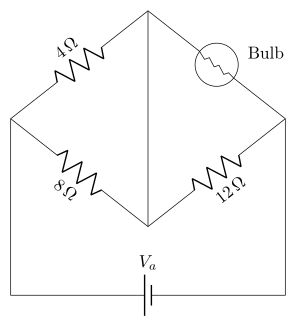
›Reveal solutionSolution
Balance demands Rbulb=6Ω. Since Rbulb=V/i=2i+1, the current must be 2.5 A; that branch (4+6=10Ω) sits across the battery, so Va=25 V — option (D).
The concept first
This question is clever because it fuses two ideas.
(1) Bridge balance. The battery is across the left and right vertices; the two paths from left vertex to right vertex are
path 1: 4Ω→bulb,path 2: 8Ω→12Ω.
The bridge is balanced when the midpoints of the two paths (the top and bottom vertices) sit at the same potential — then the diagonal carries no current. Two potential dividers reach the same fraction only if their ratios agree:
4+Rbulb4=8+128.
Equivalently Rbulb4=128 — the familiar QP=SR.
(2) A non-ohmic element. A bulb filament is not ohmic: it gets hotter as the current rises, so its resistance rises with current. That is exactly what V=i(2i+1) encodes. Its effective resistance at a given operating point is still defined by
R=iV=2i+1,
which depends on i. So demanding a particular resistance is the same as demanding a particular current — and that is the bridge to the second half of the problem.
Step-by-step
1. Impose balance.
Rbulb4=128=32⟹Rbulb=24×3=6Ω.
(Check with the potential-divider form: 4+64=0.4 and 8+128=0.4 ✓ — both midpoints sit at 40% of the way, so they are at equal potential.)
2. Convert the resistance requirement into a current.
Rbulb=iV=ii(2i+1)=2i+1=6⟹2i=5⟹i=2.5 A.
So the bulb (and hence the whole 4Ω–bulb branch, since they are in series) must carry 2.5 A.
3. Voltage across that branch. Because the galvanometer branch carries no current at balance, the 4Ω and the bulb form a simple series chain directly across the battery:
Rbranch=4+6=10Ω.
4. Find the emf.
Va=iRbranch=2.5×10=25 V.
5. Cross-check with the other branch. The 8Ω–12Ω branch has 20Ω across the same 25 V, carrying i2=25/20=1.25 A. Potential drop to the bottom vertex: 1.25×8=10 V. On the other branch, drop to the top vertex: 2.5×4=10 V. Equal — the diagonal carries no current, exactly as balance requires. ✓
6. Bonus check on the bulb. At i=2.5 A, Vbulb=i(2i+1)=2.5×6=15 V, and 4+bulb⇒10+15=25 V =Va ✓.
✓Final answerThe emf of the battery must be 25 V, so the correct option is (D).
ANSWER: D
- TG EAPCET 2024Set ap-2024-05-07-FN1 markMCQQ.The self-induced emf of a coil is 36 V. If the current in the coil is changed from 12 A to 24 A in one second, then the change in the energy stored in the coil is (A) 648 J (B) 462 J (C) 486 J (D) 572 J
›Reveal solutionSolution
The key idea is that the self-induced emf gives the inductance, and the change in stored energy is 21L(If2−Ii2). The result is 648 J, so option (A) is correct.
Concept and Intuition
The self-induced emf in a coil opposes the change in current (Lenz’s law). Its magnitude is ∣E∣=LΔtΔI, where L is the inductance. Once we find L, the energy stored in the magnetic field of an inductor is U=21LI2. The change in energy when the current changes from Ii to If is simply ΔU=21L(If2−Ii2). No integration or calculus is needed here because the current change is linear and the inductance is constant.
Step-by-step solution
- Find the inductance L from the given emf. The self-induced emf is given as 36 V. The current changes from 12 A to 24 A in 1 second, so ΔI=24−12=12A and Δt=1s. Using ∣E∣=LΔtΔI:
36=L⋅112⇒L=1236=3H.
- Calculate the initial and final stored energy. Initial energy:
Ui=21LIi2=21⋅3⋅(12)2=21⋅3⋅144=216J.
Final energy:
Uf=21LIf2=21⋅3⋅(24)2=21⋅3⋅576=864J.
- Find the change in stored energy.
ΔU=Uf−Ui=864−216=648J.
TipA shortcut: ΔU=21L(If2−Ii2)=21⋅3⋅(576−144)=21⋅3⋅432=648J. This avoids computing each energy separately.
Watch outA common mistake is to use ΔU=21L(ΔI)2 instead of the difference of squares. Here 21⋅3⋅(12)2=216J, which is not the correct change. Always use If2−Ii2.
✓Final answerThe correct option is (A).
ANSWER: A
- TG EAPCET 2024Set eng-2024-05-10-FN1 markMCQQ.The process of the loss of strength of a signal while propagating through a medium is (A) damping (B) attenuation (C) amplification (D) modulation
›Reveal solutionSolution
The loss of signal strength during propagation is called attenuation; the correct answer is (B).
The key concept here is signal degradation in transmission. When a signal travels through any medium (like a cable, optical fiber, or air), it inevitably loses energy due to resistance, scattering, or absorption. This reduction in amplitude or power is a fundamental phenomenon in physics and engineering.
Let’s clarify each option:
-
Damping – This usually refers to the reduction of oscillation amplitude in mechanical or electrical systems over time (e.g., a swinging pendulum slowing down). While related to energy loss, it’s not the standard term for signal strength loss in a propagation medium.
-
Attenuation – This is the precise, widely used term for the gradual loss of signal strength (power or amplitude) as it travels through a medium. It’s measured in decibels (dB) per unit distance. For example, in fiber optics, attenuation is caused by absorption and scattering of light.
-
Amplification – This is the opposite of loss; it increases signal strength. Clearly not the answer.
-
Modulation – This is the process of varying a carrier wave’s properties (amplitude, frequency, or phase) to encode information. It has nothing to do with signal strength loss.
Watch outA common pitfall is confusing "damping" with "attenuation." Damping is more specific to oscillatory systems (like a spring or an RLC circuit), while attenuation is the general term for signal power loss in any transmission medium.
TipThink of attenuation like a flashlight beam fading as it goes farther into fog — the light is still there, but it’s weaker. That’s exactly what happens to radio waves, electrical signals, or light in a cable.
✓Final answerThe correct option is (B).
ANSWER: B
-
- TG EAPCET 2023Set ap-2023-05-10-AN1 markMCQQ.In LCR series circuit, the current amplitude becomes 21 times its maximum value at frequencies 212 rad s−1 and 232 rad s−1. If the value of R in the circuit is 5 Ω, then the value of L is (A) 20 mH (B) 250 mH (C) 10 mH (D) 5 mH
›Reveal solutionSolution
The key idea is that the two given frequencies are the half-power points of a series RLC circuit, where the current drops to 1/2 of its peak. The bandwidth Δω=ω2−ω1 equals R/L, giving L=5/20=0.25 H=250 mH. The correct option is (B).
Concept & Intuition
In a series LCR circuit, the current amplitude is maximum at the resonant frequency ω0, where the impedance is purely resistive (Z=R). At frequencies slightly above or below resonance, the impedance increases because the net reactance ∣ωL−1/(ωC)∣ becomes nonzero, so the current drops. The frequencies at which the current falls to 1/2 of its maximum value are called the half-power points. The difference between these two frequencies is the bandwidth Δω, and for a series RLC circuit, a classic result is:
Δω=LR
This is derived from the condition that at the half-power points, the magnitude of the reactance equals the resistance: ∣ωL−1/(ωC)∣=R. For a narrow bandwidth (high Q), the two solutions are approximately ω0±R/(2L), so their difference is R/L. Even without the approximation, the exact difference between the two frequencies where ∣Z∣=2R is indeed R/L — a beautiful, exact result.
Thus, given the two frequencies and R, we can directly find L.
Step-by-step solution
- Identify the given data The two frequencies (in rad/s) are:
ω1=212,ω2=232
Resistance R=5 Ω.
These are the frequencies where current amplitude is 1/2 times its maximum — i.e., the half-power points.
- Compute the bandwidth The bandwidth is simply the difference:
Δω=ω2−ω1=232−212=20 rad/s
- Apply the series RLC bandwidth formula For a series RLC circuit, the exact bandwidth between the two half-power frequencies is:
Δω=LR
This is independent of the capacitance C and holds exactly, not just approximately.
- Solve for L Rearranging:
L=ΔωR=205=0.25 H
Convert to millihenries:
L=0.25×1000=250 mH
- Match with the options The options are: (A) 20 mH, (B) 250 mH, (C) 10 mH, (D) 5 mH. Clearly, 250 mH corresponds to option (B).
TipA common pitfall is to mistakenly use the formula Δω=R/(2L) (which is the half-bandwidth from resonance to one half-power point). Remember: the full bandwidth between the two half-power frequencies is R/L.
Watch outDo not confuse angular frequency (rad/s) with ordinary frequency (Hz). Here the units are already rad/s, so no conversion is needed. If frequencies were given in Hz, you would first convert: ω=2πf.
✓Final answerThe correct option is (B).
ANSWER: B
- TG EAPCET 2023Set eng-2023-05-13-AN1 markMCQQ.An alternating emf given by the equation E=200sin(50πt) (where E is in volts and t is in seconds) is applied across a series combination of an inductor and a resistor having inductive reactance 40 Ω and resistance 30 Ω respectively. At time t=1 s, the power dissipated by the resistor is close to (cos53∘=0.6) (A) 480 W (B) 240 W (C) 173 W (D) 307 W
›Reveal solutionSolution
i(t)=4sin(50πt−53∘); at t=1 s this is −3.2 A, so the instantaneous power in the resistor is i2R≈307 W.
Concept. In a series LR circuit the current lags the applied emf by φ with tanφ=XL/R; the instantaneous power dissipated in the resistor is i2R evaluated at that instant.
Step 1 — impedance and phase.
Z=R2+XL2=302+402=50Ω,tanφ=3040=34⇒φ=53∘.
Step 2 — current expression. Peak current I0=ZE0=50200=4 A, and the current lags:
i(t)=4sin(50πt−53∘).
Step 3 — evaluate at t=1 s. 50πrad=25×2π, i.e. exactly 25 full cycles, so sin(50π−53∘)=−sin53∘=−0.8:
i=4×(−0.8)=−3.2 A.
Step 4 — instantaneous power in R.
P=i2R=(3.2)2×30=10.24×30=307.2 W≈307 W.
✓Final answerThe power dissipated by the resistor at t=1 s is close to 307 W — option (D).
ANSWER: D
- TG EAPCET 2022Set eng-2022-07-20-FN1 markMCQQ.A capacitor of capacitance 100 μF and a coil of resistance 20 Ω and inductance 12.5 mH are connected in series with a 220 V, π200 Hz AC source. The maximum value of instantaneous current in the circuit is (A) 20 A (B) 10 A (C) 11 A (D) 15 A
›Reveal solutionSolution
The circuit is a series RLC driven by an AC source. The maximum instantaneous current is the peak current I0=V0/Z, where Z is the impedance. The answer is 11 A.
The key idea here is that in a series AC circuit, the current is not simply V/R because the inductor and capacitor each oppose the flow with a frequency-dependent reactance. The total opposition is the impedance Z, which combines resistance R, inductive reactance XL, and capacitive reactance XC. The maximum (peak) current occurs when the instantaneous voltage is at its peak, and Ohm's law for AC gives I0=V0/Z.
Let’s work through the numbers step by step.
-
Find the angular frequency ω.
The source frequency is f=π200 Hz.
Angular frequency ω=2πf=2π⋅π200=400 rad/s.
-
Compute the inductive reactance XL.
XL=ωL=400×12.5×10−3=5 Ω.
-
Compute the capacitive reactance XC.
XC=ωC1=400×100×10−61=0.041=25 Ω.
-
Find the net reactance X.
Since XL and XC oppose each other, X=XL−XC=5−25=−20 Ω.
The negative sign just means the circuit is capacitive overall; impedance uses the magnitude.
-
Calculate the impedance Z.
Z=R2+(XL−XC)2=202+(−20)2=400+400=800=202 Ω.
-
Determine the peak voltage V0.
The given 220 V is the RMS voltage. For a sinusoidal source, V0=Vrms×2=2202 V.
-
Compute the peak current I0.
I0=ZV0=2022202=20220=11 A.
Watch outA common mistake is to forget that the given voltage is RMS, not peak. Using 220 V directly as V0 would give I0=220/(202)≈7.78 A, which is not among the options. Always check whether the problem states RMS or peak.
TipNotice that the 2 factors cancel neatly here because both V0 and Z contain 2 terms. This is a handy shortcut: if the impedance has a 2 factor, the peak current often simplifies to a clean number.
✓Final answerThe maximum value of instantaneous current is 11 A, which corresponds to option (C).
-
- TG EAPCET 2022Set ap-2022-07-31-AN1 markMCQQ.A cell phone charger consists of a stepdown transformer to convert AC voltage of 120 V to AC voltage of 5.0 V. If the secondary coil contains 30 turns and charger supplies 720 mA, calculate the current in the primary coil. (A) 12 mA (B) 30 mA (C) 85 mA (D) 160 mA
›Reveal solutionSolution
For an ideal stepdown transformer, the ratio of currents is the inverse of the turns ratio. Using Ip/Is=Ns/Np, we find the primary current is 30 mA, which corresponds to option (B).
The key idea here is the transformer power balance: in an ideal transformer (no losses), the power delivered to the primary equals the power delivered by the secondary. Since power is voltage times current, this gives VpIp=VsIs. Rearranging, the current ratio is the inverse of the voltage ratio, which is also the inverse of the turns ratio. So we don’t need to know the primary voltage directly — we can use the turns ratio instead.
-
Identify the known quantities
- Secondary voltage Vs=5.0 V
- Primary voltage Vp=120 V
- Secondary turns Ns=30
- Secondary current Is=720 mA=0.720 A We need the primary current Ip.
-
Use the turns ratio to find primary turns
For a transformer, VsVp=NsNp.
So Np=Ns⋅VsVp=30⋅5.0120=30⋅24=720 turns.
-
Apply the current ratio
For an ideal transformer, IsIp=NpNs.
Therefore, Ip=Is⋅NpNs=0.720⋅72030.
Simplify: 72030=241, so Ip=0.720⋅241=0.030 A=30 mA.
TipYou can skip finding Np entirely: since VsVp=NsNp, the current ratio becomes IsIp=VpVs. So directly Ip=0.720⋅1205.0=0.720⋅241=30 mA. This is faster and avoids extra steps.
Watch outA common mistake is to invert the ratio incorrectly — students sometimes multiply by NsNp instead of NpNs. Remember: higher voltage side has lower current, so the primary (120 V) should have a much smaller current than the secondary (5 V). 30 mA is indeed much smaller than 720 mA, which checks out.
✓Final answerThe correct option is (B).
ANSWER: B
-
- TG EAPCET 2021Set ap-2021-08-09-FN1 markMCQQ.A light bulb is rated at 110 W for a 220 V supply. The resistance of the bulb is (A) 440 Ω (B) 220 Ω (C) 55 Ω (D) 110 Ω
›Reveal solutionSolution
Using the power rating and voltage, we apply P=V2/R to find the resistance. The bulb’s resistance is 440 Ω, so the correct option is (A).
The key concept here is the relationship between electrical power, voltage, and resistance for a device operating under steady conditions. A light bulb’s rating (110 W at 220 V) tells us the power it consumes when connected to a 220 V supply. Since the bulb is a resistive load (it heats up and glows), we can use the formula P=V2/R, which comes from combining Ohm’s law (V=IR) with the power formula P=VI. This avoids needing the current, which isn’t given.
Why this works: The bulb’s resistance is assumed constant (though in reality it changes with temperature, the problem treats it as fixed for calculation). The formula P=V2/R directly links the three quantities, so rearranging gives R=V2/P.
Now, step by step:
-
Identify the given values:
Power P=110 W, voltage V=220 V.
-
Recall the power formula for a resistor:
P=RV2. This is derived from P=VI and V=IR, eliminating I.
-
Rearrange to solve for resistance R:
Multiply both sides by R: PR=V2.
Then divide by P: R=PV2.
-
Substitute the numbers:
R=110(220)2=11048400.
-
Simplify:
48400÷110=440. So R=440 Ω.
TipA common shortcut: 2202=48400, and dividing by 110 is the same as multiplying by 1/110. Notice 48400/110=4840/11=440 — you can cancel a factor of 10 first.
Watch outA classic mistake is to use P=I2R or P=VI without finding current first, leading to errors. Always pick the formula that uses the two given quantities directly — here P and V — to avoid extra steps.
Thus, the bulb’s resistance is 440 Ω, which matches option (A).
✓Final answerThe correct option is (A).
ANSWER: A
-
🎓Unlock everything free for 14 days
- ✓Full step-by-step solutions
- ✓Concept-first explanations
- ✓Methods, shortcuts & mistakes
- ✓PYQ mapping + timed mock tests
Full access for 14 days. No credit card required.