Q.A galvanometer of resistance 10 Ω that gives maximum (full-scale) deflection for a current of 1 mA is to be converted into a multirange voltmeter reading 2 V, 20 V and 200 V. Three resistors R1, R2 and R3 are joined in series with the galvanometer, one after another. The 2 V terminal is tapped just after R1, the 20 V terminal after the series pair R1+R2, and the 200 V terminal after R1+R2+R3; each range terminal together with the common galvanometer terminal forms the two leads of the voltmeter for that range. Find R1, R2 and R3.
🔒You're viewing a preview — the full solution, concept, methods & PYQ mapping are locked.
🔒 Start your 14-day free trial to unlock the full solution →Concept understanding — Galvanometer to Voltmeter Conversion
Galvanometer to Voltmeter Conversion
A moving-coil galvanometer deflects fully only at a small current Ig (its full-scale deflection current) and has internal resistance G. To use it as a voltmeter — reading much larger voltages V — a large resistance Rs (the multiplier) is connected in series with the galvanometer coil. This series resistance limits the current to exactly Ig when the full-scale voltage V is applied, so the needle deflects fully and the scale is recalibrated to read volts instead of amperes.
The Conversion Formula
The galvanometer and Rs together form a series circuit of total resistance Rs+G. Applying V across this series combination drives a current
I=Rs+GV
We want this current to equal Ig exactly when V is the maximum (full-scale) voltage, so Ig=Rs+GV, which rearranges to:
Rs=IgV−G
Since the coil's deflection is proportional to the current through it, and that current is proportional to the applied voltage (Ohm's law), the resulting scale is linear in V: equal voltage steps give equal angular deflections.
Why series, not parallel?
A voltmeter must be connected across the component whose voltage is being measured, without diverting current away from it — so it should draw as little current as possible, meaning its own resistance must be as large as possible. Adding Rs in series does exactly that: it raises the meter's total resistance to Rs+G, which is deliberately made large. (This is the opposite requirement to an ammeter, which sits in the current path and needs the smallest possible resistance — achieved there with a small shunt in parallel, not a large resistor in series.)
Worked Example
For Ig=1 mA, G=50 Ω, converting to a 0–10 V voltmeter:
Rtotal=IgV=0.00110=10,000 Ω⟹Rs=10,000−50=9,950 Ω
A 9.95 kΩ resistor in series gives full-scale deflection at exactly 10 V.
Do not forget to subtract G from V/Ig. For most galvanometers G is small next to Rs, but in precision work it matters.
Key Properties
- High input resistance: Rv=Rs+G is large (kΩ to MΩ), so the voltmeter draws minimal current and barely disturbs the circuit it measures.
- Linear scale: deflection ∝ current ∝ voltage. …
A voltmeter reads V=Ig(G+Rseries) at full-scale. With Ig=1 mA and G=10 Ω, each higher range simply adds more series resistance. This gives R1=1990 Ω, R2=18 kΩ, R3=180 kΩ. …
To read a voltage V, a galvanometer must carry only its full-scale current Ig when that voltage is across the branch, so V=Ig(G+Rseries). Adding the three series resistors in turn raises the range from 2 V to 20 V to 200 V, giving R1=1990 Ω, R2=18 kΩ and R3=180 kΩ.
Concept & formula
A galvanometer becomes a voltmeter of range V by placing a large resistance R in series so that at the full-scale current Ig the total voltage drop equals V:
V=Ig(G+R).
Here G=10 Ω and Ig=1 mA=10−3 A, so Ig is common to every range and the resistance in the loop increases as R1, then R1+R2, then R1+R2+R3.
Step 1 — the 2 V range (galvanometer +R1)
2=Ig(G+R1)=10−3(10+R1) ⇒ 10+R1=2000 ⇒ R1=1990 Ω.
Step 2 — the 20 V range (galvanometer +R1+R2) …
Method: Designing a Multi-Range Voltmeter From a Single Galvanometer
General technique for any "convert this galvanometer into a voltmeter with ranges V1,V2,V3,…" problem, whether the resistors are separate branches or one series chain tapped at intermediate points.
Steps
Step 1: Write the governing equation for full-scale deflection
At full-scale the current through the galvanometer coil is always exactly Ig, and Ohm's law across the SERIES combination of the coil resistance G and whatever series resistance is in the current path gives:
V=Ig(G+Rseries)
Step 2: Identify what "series resistance" means for each range, from how the taps are wired
If the range terminals are taps along one resistor chain, the resistance in the loop for the n-th range is the SUM of every resistor up to that tap (R1, then R1+R2, then R1+R2+R3, …) — not just the newly added resistor alone.
Step 3: Solve the equations in order, from the smallest range up …
Showing the 12 most recent of 21 on this concept.
- TG EAPCET 2025Set eng-2025-05-02-FN1 markMCQQ.The power of an electric motor is 242 W when connected to a 220 V supply. When the motor is operated at 200 V, the current drawn by it is (A) 1.21 A (B) 1.1 A (C) 1.5 A (D) 1 A
›Reveal solutionSolution
The motor's resistance is R=V2/P=200 Ω; at 200 V the current is I=V/R=1 A — option (D).
Concept
At 220 V the motor draws 242 W, fixing its effective resistance R=PV2. Treating R as constant, the current at a new voltage is I=RV.
Solution …
- TG EAPCET 2025Set eng-2025-05-03-AN1 markMCQQ.A straight uniform wire of resistance 36 Ω is bent in the form of a semi-circular loop. The effective resistance between the ends of the diameter of the semi-circular loop is (A) 956 Ω (B) 736 Ω (C) 799 Ω (D) 977 Ω
›Reveal solutionSolution
The wire is bent into a semicircle, so the total resistance is split into two arcs in parallel. The effective resistance between the diameter ends is 736Ω, which corresponds to option (B).
Concept & Intuition
When a uniform wire is bent into a shape, the resistance of any segment is proportional to its length. Here, the wire forms a semicircular loop. The two ends of the diameter are the endpoints of the semicircle. The current can travel from one end to the other along two paths: the upper arc and the lower arc (which together make the full semicircle). These two arcs are connected in parallel between the same two points. So the problem reduces to finding the resistances of those two arcs and then combining them in parallel.
-
Total resistance and total length
The straight wire has resistance 36Ω. When bent into a semicircle, the total length is unchanged, so the total resistance remains 36Ω. The wire forms a semicircular arc; the two ends of the diameter are the endpoints of this arc.
-
Divide the wire into two arcs
The semicircle is exactly half of a full circle. The two arcs between the diameter ends are:
- The upper arc (the semicircular arc itself)
- The lower arc (the straight diameter? No — the wire is only the semicircular loop, so the lower arc is actually the other half of the circle? Wait: The wire is bent into a semi-circular loop, meaning it is just the curved part, not including the diameter. So the two paths between the ends are:
- Path 1: the curved semicircular wire (length = half the circumference of a full circle)
- Path 2: the straight line along the diameter? But the wire is only the semicircle; there is no wire along the diameter. So the only conducting path is the curved wire itself. That would mean the resistance between the ends is just the resistance of the whole wire, 36Ω — but that is not among the options. So the interpretation must be different.
Correction: The phrase "bent in the form of a semi-circular loop" means the wire is shaped into a semicircle including the diameter? No — a loop implies the wire forms the entire boundary of a semicircular region: the curved arc and the straight diameter. But the problem says "a straight uniform wire of resistance 36Ω is bent in the form of a semi-circular loop." That means the wire is reshaped into a semicircle (the curved part only), and the two ends are the ends of the diameter. However, the diameter itself is not part of the wire. So how can current flow? It flows along the curved wire from one end to the other. That gives 36Ω, which is not an option.
The intended meaning: The wire is bent into a complete circular loop? No — it says semi-circular. Let's check the options: they are all less than 36Ω, so the effective resistance is smaller, implying parallel paths. The only way to get parallel paths is if the wire forms a closed shape where the two ends of the diameter are connected by two arcs. That happens if the wire is bent into a full circle and then we consider the ends of a diameter? But the problem says "semi-circular loop".
Key insight: A "semi-circular loop" often means the wire is shaped like a semicircle with the diameter also made of the same wire. That is, the wire forms the entire boundary of a semicircle: the curved arc plus the straight diameter. The total length is the sum of the curved part and the straight part. Since the wire is uniform, the resistance of each part is proportional to its length.
-
Determine lengths
Let the radius of the semicircle be r.
- Length of curved arc = πr
- Length of straight diameter = 2r Total length = πr+2r=r(π+2) Total resistance = 36Ω. So resistance per unit length = r(π+2)36.
-
Resistances of the two paths
Between the two ends of the diameter, there are two parallel paths: …
-
- TG EAPCET 2025Set eng-2025-05-03-FN1 markMCQQ.The potential difference between the terminals of a cell is 20 V when a current of 2 A flows through the circuit. When the direction of current in the circuit is reversed, the potential difference between the terminals of the cell is 30 V. The internal resistance of the cell is (A) 2 Ω (B) 1.5 Ω (C) 2.5 Ω (D) 1 Ω
›Reveal solutionSolution
The key idea is that the terminal voltage changes with current direction because the internal resistance always opposes the current; solving the two circuit equations gives the internal resistance as 2.5 Ω.
Concept and Intuition
A real cell has an internal resistance r in series with its ideal emf E. The terminal voltage V is E−Ir when the current flows from the positive to the negative terminal inside the cell (normal discharge). If we reverse the current (forcing current into the positive terminal, as in charging), the terminal voltage becomes E+Ir because the internal resistance now drops voltage in the opposite sense. The problem gives two different terminal voltages for opposite current directions, so we can set up two equations and solve for r.
Step-by-step solution
-
Define variables
Let E be the emf of the cell and r its internal resistance. The current magnitude is I=2 A in both cases, but the direction changes.
-
First case: normal discharge
Current flows out of the positive terminal. The terminal voltage is lower than the emf by Ir:
V1=E−Ir=20 V.
- Second case: reversed current Current is forced into the positive terminal (charging). Now the terminal voltage is higher than the emf by Ir:
V2=E+Ir=30 V.
- Solve the system Subtract the first equation from the second:
(E+Ir)−(E−Ir)=30−20
2Ir=10
r=2I10=2×210=410=2.5 Ω. …
-
- TG EAPCET 2025Set eng-2025-05-04-AN1 markMCQQ.729 small identical spheres each charged to an electric potential 3V combine to form a bigger sphere. The electric potential of the bigger sphere is (A) 9 V (B) 729 V (C) 81 V (D) 243 V
›Reveal solutionSolution
When small charged spheres merge, charge is conserved but the radius changes; the potential of the big sphere is 3V×(729)2/3=3V×81=243V, so the answer is (D).
The key idea is that electric potential of a conducting sphere depends on both its total charge and its radius. When many identical small spheres merge into one big sphere, the total charge adds up, but the radius grows only as the cube root of the number of spheres (since volume is additive). The potential scales as V∝Q/R, so we need to see how Q and R change together.
Step-by-step reasoning
- Potential of a single small sphere For a conducting sphere of radius r carrying charge q, the potential at its surface is
Vsmall=rkq=3V.
So kq/r=3.
- Charge and volume when merging
There are N=729 identical small spheres.
- Total charge: Qbig=Nq=729q.
- Total volume: Vbig=N⋅34πr3. The big sphere has radius R such that
34πR3=729⋅34πr3⇒R3=729r3.
Hence R=3729r=9r (since 93=729).
- Potential of the big sphere Using the same formula:
Vbig=RkQbig=9rk(729q).
Factor out the small-sphere potential:
Vbig=9729⋅rkq=81⋅(3V)=243V.
- Why not simply add potentials? …
- TG EAPCET 2025Set eng-2025-05-04-FN1 markMCQQ.729 small identical spheres each charged to an electric potential 3V combine to form a bigger sphere. The electric potential of the bigger sphere is (A) 9 V (B) 729 V (C) 243 V (D) 81 V
›Reveal solutionSolution
When small charged spheres merge, charge is conserved and volume is conserved. The potential of the big sphere is 3V×(729)2/3=3V×81=243 V.
The key idea is that electric potential of a charged sphere depends on both its total charge and its radius. When identical small spheres merge, the total charge adds up, but the radius also changes because the volume of the big sphere equals the sum of the volumes of the small ones. You cannot simply multiply the potential by the number of spheres — that would ignore the change in size.
Let each small sphere have radius r and charge q. Its potential is Vsmall=4πϵ01rq=3 V.
When 729 such spheres combine, the total charge becomes Q=729q. The big sphere's volume is 729 times the volume of one small sphere: 34πR3=729×34πr3, so R3=729r3, giving R=3729r=9r.
Now the potential of the big sphere is Vbig=4πϵ01RQ=4πϵ019r729q=4πϵ01rq×9729=3 V×81=243 V. …
- TG EAPCET 2025Set ap-2025-04-29-AN1 markMCQQ.When a cell is connected across a resistance R, the current through it is 0.7 A and when the same cell is connected across a resistance 2R, the current through it is 0.42 A. If the same cell is connected across a resistance 3R, the current through it is (A) 0.4 A (B) 0.3 A (C) 0.25 A (D) 0.35 A
›Reveal solutionSolution
This problem uses Ohm's law for a circuit with internal resistance to find the cell's EMF and internal resistance, then calculates the current for a new external resistance. The current when connected across 3R is 0.3 A.
The core concept here is understanding how a real cell behaves in a circuit. An ideal cell would provide a constant voltage (its electromotive force, EMF) regardless of the current drawn. However, real cells have an internal resistance, which causes a voltage drop within the cell itself when current flows. This means the actual voltage available to the external circuit (the terminal voltage) is less than the EMF.
When a cell with EMF E and internal resistance r is connected to an external resistance R, the total resistance in the circuit is the sum of the external and internal resistances, R+r. According to Ohm's Law, the current I flowing through the circuit is given by:
I=R+rE
This formula is key to solving the problem. We will use the given information from the first two scenarios to determine the unknown EMF (E) and internal resistance (r) of the cell. Once E and r are known, we can calculate the current for the third scenario.
-
Set up equations for the given scenarios:
We are given two situations where the cell is connected to different external resistances, and the corresponding currents are measured. Let E be the EMF of the cell and r be its internal resistance.
-
Scenario 1: External resistance is R, current is 0.7 A.
Using the formula I=R+rE, we get:
0.7=R+rE
This can be rewritten as:
E=0.7(R+r) (Equation 1)
-
Scenario 2: External resistance is 2R, current is 0.42 A.
Similarly, for this scenario:
0.42=2R+rE
This can be rewritten as:
E=0.42(2R+r) (Equation 2)
-
-
Solve for the internal resistance (r) in terms of R:
Since the EMF (E) of the cell is constant, we can equate Equation 1 and Equation 2:
0.7(R+r)=0.42(2R+r)
Expand both sides:
0.7R+0.7r=0.84R+0.42r
Now, gather terms involving r on one side and terms involving R on the other:
0.7r−0.42r=0.84R−0.7R
0.28r=0.14R
To find r, divide both sides by 0.28:
r=0.280.14R
r=0.5R
So, the internal resistance of the cell is half of the initial external resistance R.
-
Solve for the EMF (E) in terms of R: …
-
- TG EAPCET 2025Set ap-2025-04-29-FN1 markMCQQ.If the magnitude of electric field in a conductor is 200NC−1 and the current density is 109Am−2, then the resistivity of the material of the conductor is (A) 5×10⁶Ωm (B) 2×10¹¹Ωm (C) 2×10⁻⁷Ωm (D) 1800Ωm
›Reveal solutionSolution
The resistivity of a material is defined by the ratio of the electric field to the current density within it. Using the given values, the resistivity is calculated as 2×10⁻⁷Ωm.
Concept and Intuition
When an electric field is applied across a conductor, it exerts a force on the free charge carriers (electrons), causing them to drift and constitute an electric current. The ease with which these charge carriers move through the material determines its conductivity, and conversely, the resistance to this flow is quantified by its resistivity.
Resistivity (ρ) is an intrinsic property of a material that describes how strongly it resists the flow of electric current. A high resistivity means the material is a poor conductor (or a good insulator), while a low resistivity indicates a good conductor.
The relationship between the electric field (E) inside a conductor, the current density (J) flowing through it, and the material's resistivity (ρ) is given by the microscopic form of Ohm's Law:
E=ρJ
where E is the electric field magnitude, J is the current density, and ρ is the resistivity.
This equation tells us that for a given current density, a higher electric field is required to drive that current through a material with higher resistivity. Conversely, for a given electric field, a material with lower resistivity will allow a higher current density.
To find the resistivity, we can rearrange this formula:
ρ=JE
Step-by-Step Solution
-
Identify the given quantities:
We are given the magnitude of the electric field, E=200NC−1.
We are also given the current density, J=109Am−2.
-
Recall the relevant formula:
The relationship between electric field (E), current density (J), and resistivity (ρ) is given by the microscopic form of Ohm's Law:
E=ρJ
-
Rearrange the formula to solve for resistivity:
To find the resistivity, we can express ρ as the ratio of E to J:
ρ=JE
-
Substitute the given values into the formula: …
-
- TG EAPCET 2024Set eng-2024-05-09-FN1 markMCQQ.Three resistors of resistances 10 Ω, 20 Ω and 30 Ω are connected as shown in the figure. If the points A, B and C are at potentials 10 V, 6 V and 5 V respectively, then the ratio of the magnitudes of the currents through 10 Ω and 30 Ω resistors is [FIGURE] (A) 1:3 (B) 3:1 (C) 1:2 (D) 2:1
›Reveal solutionSolution
The key idea is to apply Kirchhoff’s current law at the central junction and Ohm’s law to each resistor, using the given potentials. The ratio of currents through the 10 Ω and 30 Ω resistors is found to be 2:1, so the correct option is (D).
We have three resistors connected in a Y-shaped (or star) configuration, with each resistor’s other end connected to a known potential: A at 10 V, B at 6 V, C at 5 V. The central point (let’s call it O) is at some unknown potential VO. The current through each resistor is determined by the potential difference across it, divided by its resistance. The trick is that the currents must satisfy Kirchhoff’s current law at O: the sum of currents entering O equals the sum leaving O. This gives us an equation to find VO, and then we can compute the individual currents.
- Label currents and apply Ohm’s law Let I10, I20, I30 be the currents through the 10 Ω, 20 Ω, and 30 Ω resistors, respectively. Assume all currents flow toward the central point O (this is a convenient sign convention; if a current turns out negative, it just means it actually flows away). By Ohm’s law:
I10=10VA−VO=1010−VO
I20=20VB−VO=206−VO
I30=30VC−VO=305−VO
- Apply Kirchhoff’s current law at O The sum of currents entering O must be zero (since no charge accumulates). With our sign convention (all assumed toward O), we have:
I10+I20+I30=0
Substitute the expressions:
1010−VO+206−VO+305−VO=0
- Solve for VO Multiply through by the least common multiple of 10, 20, 30, which is 60:
6(10−VO)+3(6−VO)+2(5−VO)=0
Expand:
60−6VO+18−3VO+10−2VO=0
Combine constants and VO terms:
(60+18+10)−(6+3+2)VO=88−11VO=0
Hence:
11VO=88⇒VO=8 V
- Compute the currents Now plug VO=8 V back into the Ohm’s law expressions:
I10=1010−8=102=0.2 A
- TG EAPCET 2024Set ap-2024-05-07-AN1 markMCQQ.A cell of emf 2 V is connected to an external resistor. If the current through the resistor is 200 mA and the terminal voltage of the cell is 87.5% of the emf of the cell, then the internal resistance of the cell is (A) 1.50 Ω (B) 1.25 Ω (C) 2 Ω (D) 2.25 Ω
›Reveal solutionSolution
The internal resistance is found by applying the terminal voltage formula V=ε−Ir and using the given percentage. The internal resistance comes out to be 1.25 Ω, which is option (B).
The core idea here is that a real cell isn't a perfect voltage source — it has an internal resistance r in series with its emf ε. When current flows, some voltage drops across this internal resistance, so the terminal voltage V (the voltage you actually measure across the cell's terminals) is less than the emf. The relationship is V=ε−Ir, where I is the current.
The problem gives you the emf, the current, and tells you that the terminal voltage is 87.5% of the emf. That percentage is the key — it directly tells you how much voltage is "lost" inside the cell, and from that loss you can find r.
-
Write down what's given.
Emf ε=2 V.
Current I=200 mA=0.2 A (always convert to amperes).
Terminal voltage V=87.5% of ε=0.875×2=1.75 V.
-
Apply the terminal voltage equation.
The voltage drop across the internal resistance is Ir, and it subtracts from the emf:
V=ε−Ir
Substitute the known values:
1.75=2−(0.2)r
- Solve for r. Rearranging: 0.2r=2−1.75=0.25 …
-
- TG EAPCET 2024Set ap-2024-05-07-FN1 markMCQQ.The power gain of a transistor operating in common emitter configuration is 32,000. If the input and output resistances of the circuit are 1200 Ω and 6000 Ω respectively, then the current gain is (A) 8000 (B) 800 (C) 80 (D) 6400
›Reveal solutionSolution
The power gain of a transistor is the product of current gain and voltage gain; using the given resistances, the current gain is found to be 800, which corresponds to option (B).
The key concept here is the relationship between power gain, current gain, and voltage gain in a common emitter transistor amplifier. Power gain (AP) is defined as the ratio of output power to input power. Since power = (current)² × resistance or = voltage × current, we can express power gain in terms of current gain (AI) and voltage gain (AV) as:
AP=AI×AV
But voltage gain itself depends on current gain and the resistances: AV=AI×RinRout. Combining these gives a direct formula linking power gain, current gain, and resistances.
Why this approach works: Instead of solving for two unknowns, we use the fact that power gain is given, and the resistances are known, so we can solve for current gain directly.
Let’s work through it step by step.
- Write the formula for power gain in terms of current gain. The voltage gain for a common emitter amplifier is:
AV=VinVout=IinRinIoutRout=AI×RinRout
Then power gain:
AP=AI×AV=AI×(AI×RinRout)=AI2×RinRout
- Substitute the given values. We have AP=32,000, Rin=1200 Ω, Rout=6000 Ω. So:
32000=AI2×12006000
Simplify the resistance ratio:
12006000=5
Thus:
- TG EAPCET 2023Set eng-2023-05-12-FN1 markMCQQ.In a transistor, the base current is 10μA and the emitter current is 1mA, then the collector current is (A) 990μA (B) 100μA (C) 1010μA (D) 90μA
›Reveal solutionSolution
In a bipolar junction transistor, the collector current is the emitter current minus the base current, so IC=1mA−10μA=990μA. The correct option is (A).
The key idea here is current conservation in a transistor. A bipolar junction transistor (BJT) has three terminals: emitter, base, and collector. The currents at these terminals are related by a simple but fundamental rule: the current entering the emitter must equal the sum of the currents leaving the base and collector (or vice versa, depending on the direction). For an NPN transistor in normal active mode, the emitter current IE is the sum of the base current IB and the collector current IC:
IE=IB+IC
This is not an approximation—it’s a direct consequence of Kirchhoff’s current law applied to the transistor as a node. So if we know any two currents, we can always find the third.
Let’s work through it step by step.
-
Identify the given values.
Base current: IB=10μA
Emitter current: IE=1mA
Note the units: 1mA=1000μA. It’s helpful to convert everything to the same unit to avoid mistakes.
-
Apply the current relation.
From IE=IB+IC, we solve for the collector current:
IC=IE−IB
- Substitute the numbers. IC=1000μA−10μA=990μA …
-
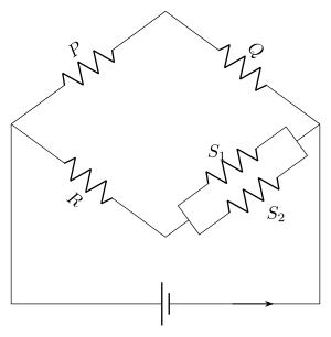
- TG EAPCET 2023Set eng-2023-05-13-AN1 markMCQQ.As shown in the figure, in a Wheatstone’s bridge, three resistances P, Q and R are connected in the three arms and the fourth arm is formed by two resistances S1 and S2 connected in parallel. The condition for the bridge to be balanced is (A) QP=S1+S22R (B) QP=S1S2R(S1+S2) (C) QP=2S1S2R(S1+S2) (D) QP=S1+S2R
›Reveal solutionSolution
Replace the parallel pair by Seff=S1S2/(S1+S2) and put it into P/Q=R/S. That gives QP=S1S2R(S1+S2) — option (B).
The concept first: what "balanced" really means
A Wheatstone bridge is balanced when no current flows through the galvanometer, which happens precisely when the two junctions it connects are at the same potential. Under that condition the current I1 flows undivided through P then Q, and I2 through R then the fourth arm. Equal potentials at the mid-points give
I1P=I2RandI1Q=I2S
Dividing one by the other eliminates the currents entirely:
QP=SR
That is the whole balance condition — and notice it involves only the ratios, never the battery emf or its internal resistance. This is why the bridge is such a precise instrument.
The only twist in this question is that the "S" arm is not a single resistor. But the bridge does not care how the arm is built; it only sees the equivalent resistance between that arm's two nodes.
Step-by-step
Step 1 — Collapse the fourth arm. S1 and S2 are in parallel (both connected between the same two nodes):
Seff1=S11+S21=S1S2S1+S2⟹Seff=S1+S2S1S2
Step 2 — Write the balance condition.
QP=SeffR …
🎓Unlock everything free for 14 days
- ✓Full step-by-step solutions
- ✓Concept-first explanations
- ✓Methods, shortcuts & mistakes
- ✓PYQ mapping + timed mock tests
Full access for 14 days. No credit card required.