Q.Two identical current carrying coaxial loops, carry current I in an opposite sense. A simple amperian loop passes through both of them once. Calling the loop as C,
🔒You're viewing a preview — the full solution, concept, methods & PYQ mapping are locked.
🔒 Start your 14-day free trial to unlock the full solution →Concept understanding — Magnetic Force Balance
Magnetic Force Balance
When a current-carrying wire or coil sits in a magnetic field, it feels a force F=BILsinθ (or, for a point charge, F=qvBsinθ). On its own that force just pushes the conductor - but in many real situations the push is deliberately set up to CANCEL another force, so the whole system sits in equilibrium. That equilibrium condition - magnetic force balanced against weight, against another wire's magnetic force, or against a mechanical counterweight - is what "magnetic force balance" means, and it is also historically how the ampere itself was defined.
The balance condition
Whenever a conductor is in equilibrium under a magnetic force and one other force, the two must be equal and opposite:
BILsinθ=Fother
Solving this equation for whichever quantity is unknown (B, I, L, or the other force) is the entire skill in this class of problem - the only new step, beyond the force law itself, is correctly identifying what the magnetic force is opposing.
Case 1: a wire suspended against gravity
A straight horizontal wire of mass m and length l, carrying current I, can be held up ("floated") in mid-air by a horizontal magnetic field perpendicular to it. The upward magnetic force must equal the downward weight:
BIl=mg⟹B=Ilmg
For example, a 200g, 1.5m wire carrying 2A needs B=(2)(1.5)(0.2)(9.8)≈0.65T to stay suspended.
Case 2: two wires balancing each other
Two long parallel wires carrying currents I1,I2 exert a force per unit length on each other of 2πdμ0I1I2 (attractive if the currents run the same way, repulsive if opposite). If one wire is free to move, this magnetic force can itself balance that wire's weight:
2πhμ0I2L=mg⟹h=2πmgμ0I2L
This is exactly how a "current balance" apparatus works, and historically it is how the ampere was defined: the current that, flowing in two infinite parallel wires one metre apart, produces a force of exactly 2×10⁻⁷N per metre of length.
Case 3: balancing on a beam
A current-carrying coil arm hanging from one pan of a beam balance feels an extra force F=NBIl when only that arm sits in an external field. Re-balancing the beam means adding a mass m so that mg=NBIl.
Always check which length enters the formula - for a coil of N turns the force multiplies by N; for a single suspended straight wire it doesn't. …
Why this formula?
Magnetic Force Balance: Why the Key Formulas Hold
The Magnetic Force Balance describes when the magnetic force on a charged particle or current-carrying conductor is exactly balanced by another force (gravity, electric force, or tension). Let's build the reasoning step-by-step.
1. The Core Idea: What Does "Balance" Mean?
A force balance means the net force on an object is zero:
Fnet=0
For magnetic forces we use the Lorentz force law:
- On a moving charge: Fm=q(v×B)
- On a current-carrying wire: Fm=I(L×B)
When this is balanced by another force (say gravity Fg=mg):
Fm+Fother=0
2. Case 1: Charged Particle in Crossed Fields (Velocity Selector)
A charged particle moves perpendicular to both electric field E and magnetic field B.
- Electric force: Fe=qE (along E)
- Magnetic force: Fm=q(v×B) (perpendicular to both v and B)
For straight-line motion (no deflection), the two forces must cancel:
qE=qvB⇒v=BE
Key insight: Only particles with this exact speed pass undeflected — this is how velocity selectors work in mass spectrometers.
3. Case 2: Current-Carrying Wire Balanced by Gravity
A horizontal wire carrying current I sits in a perpendicular magnetic field B, suspended by strings.
The magnetic force on a straight wire is Fm=ILBsinθ; for a wire perpendicular to the field (θ=90∘), Fm=ILB. Setting this equal to the weight Fg=mg for equilibrium:
ILB=mg
Key insight: This balance lets you measure B if I, L, and m are known — the principle behind a current balance experiment.
4. Case 3: Circular Motion of a Charged Particle …
By Ampere's law, ∮CB⋅dl=μ0Ienc. The loop C threads both coaxial loops once, and they carry equal but opposite currents, so Ienc=I−I=0, hence ∮CB⋅dl=0.
- This is zero regardless of the sense C is traversed in (reversing sense just flips the sign of an already-zero quantity) - option (b) true. …
The net current enclosed by C is zero for either sense of traversal, so ∮CB⋅dl=0 regardless of the sense of C - matching options (b) and (c).
Setting up Ampere's law
∮CB⋅dl=μ0Ienc
The two coaxial loops carry equal current I but in opposite senses. The amperian loop C threads through both of them exactly once, so
Ienc=I−I=0⇒∮CB⋅dl=0.
Checking (a)
(a) claims ∮CB⋅dl=∓2μ0I. This double-counts the current as if both loops contributed with the same sign; since they are opposite, the terms cancel to zero, not 2μ0I. (a) is false.
Checking (b)
Reversing the sense in which C is traversed flips the sign of Ienc (from I−I to −(I−I)), but since Ienc=0 either way, the value of the line integral is 0 regardless of which sense C is traversed. (b) is true.
Checking (c) …
Method: Ampere's Law With Cancelling Currents -- Zero Circulation Doesn't Mean Zero Field
When an Amperian loop encloses currents of opposite sign that cancel, the technique is to compute the net enclosed current first, then reason carefully about what a zero circulation implies (and does not imply) about the field itself along that path.
Steps
Step 1: Compute the net enclosed current with correct signs
∮CB⋅dl=μ0Ienc
Assign a sign to each current based on the right-hand-rule convention matching your chosen sense of traversal around C. If C threads two currents of equal magnitude but opposite direction, Ienc is their signed sum -- here I−I=0.
Step 2: Check what happens if you reverse the sense of C
Reversing the traversal direction flips the sign of every enclosed current simultaneously, so it flips the sign of Ienc (and hence of the integral) as a whole. If Ienc was already zero, flipping its sign leaves it zero -- so a vanishing circulation is the same for either sense of traversal.
Step 3: Do not conclude the field itself is zero along C …
Showing the 12 most recent of 17 on this concept.
- TG EAPCET 2026Set eng-2026-05-10-AN1 markMCQQ.Two long straight parallel wires P and Q carrying currents of 10A and 20A respectively in the same direction are placed in air with a separation of 10cm between them. Another long straight wire R carrying a current of 5A in the opposite direction is placed between the wires P and Q and parallel to them at a distance of 5cm from wire Q. Then the magnitude of the net force acting on wire R per unit length is (A) 6×10⁻⁴ Nm−1 (B) 2×10⁻⁴ Nm−1 (C) 4×10⁻⁴ Nm−1 (D) 8×10⁻⁴ Nm−1
›Reveal solutionSolution
R sits midway between P and Q. Both P and Q repel R (opposite currents), but from opposite sides, so the forces subtract: net =4×10⁻⁴−2×10−4=2×10⁻⁴ N m−1.
Setup
- Wire P: IP=10 A; Wire Q: IQ=20 A (same direction), separation 10 cm.
- Wire R: IR=5 A in the opposite direction, placed between them at 5 cm from Q — hence also 5 cm from P (exactly midway).
Force per unit length between two parallel wires:
LF=2πdμ0I1I2,2πμ0=2×10⁻⁷
Force on R due to P (d=0.05 m):
LFP=0.05(2×10⁻⁷)(10)(5)=2×10⁻⁴ N m−1
Opposite currents ⇒ repulsion, pushing R away from P (toward Q).
Force on R due to Q (d=0.05 m): …
- TG EAPCET 2026Set eng-2026-05-11-FN1 markMCQQ.A long solenoid having 15 cm circumference and 70 turns per metre is carrying a current of 2A. The magnetic field inside the solenoid at a distance 1 cm from the surface and the magnetic field outside the solenoid respectively are (A) 0,1.76×10−4 T (B) 8.8×10⁻³ T,0 (C) 1.76×10⁻⁴ T,0 (D) 0,8.8×10−3 T
›Reveal solutionSolution
For an ideal solenoid, the magnetic field is uniform inside and zero outside. The given circumference is irrelevant because the field depends only on turns per metre and current. Inside: B=μ0nI=1.76×10⁻⁴ T; outside: B=0. The correct option is (C).
The key concept is the magnetic field of an ideal solenoid. An ideal solenoid is infinitely long and tightly wound, so the field lines are parallel inside and zero outside. The field inside is uniform and given by B=μ0nI, where n is the number of turns per unit length and I is the current. The circumference given (15 cm) is a red herring — it does not affect the field magnitude inside or outside for an ideal solenoid.
-
Identify the relevant parameters.
- Turns per metre: n=70 turns/m
- Current: I=2 A
- Permeability of free space: μ0=4π×10−7 T⋅m/A
- The distance from the surface (1 cm) is irrelevant for an ideal solenoid — inside, the field is uniform everywhere; outside, it is zero everywhere.
-
Compute the magnetic field inside the solenoid.
Using B=μ0nI:
B=(4π×10−7)×70×2
First, 70×2=140.
Then 4π×10−7×140=560π×10−7=5.6π×10−5.
Using π≈3.1416, 5.6×3.1416≈17.593, so
B≈1.7593×10⁻⁴ T≈1.76×10⁻⁴ T.
- Determine the magnetic field outside the solenoid. …
-
- TG EAPCET 2026Set ap-2026-05-05-FN1 markMCQQ.A long horizontal straight wire P carrying a current of 120 A is fixed and another horizontal straight wire Q of linear mass density 1.2×10⁻² kg m−1 is placed 2.5 cm below wire P. If the wire Q remains suspended in equilibrium in air, then the current through it is (Acceleration due to gravity =10 ms−2) (A) 225 A (B) 75 A (C) 250 A (D) 125 A
›Reveal solutionSolution
The key idea is that the magnetic force per unit length on wire Q due to wire P must exactly balance the weight per unit length of wire Q. Using the formula for force between parallel currents, the required current in Q is found to be 125 A.
The problem is about two parallel current-carrying wires. When two long straight wires carry currents, they exert a magnetic force on each other — attractive if the currents are in the same direction, repulsive if opposite. Here, wire Q is suspended below wire P and remains in equilibrium, meaning the net force on it is zero. The only forces acting on Q are its weight (downward) and the magnetic force from P (which must be upward to balance). So the magnetic force must be repulsive, implying the currents in P and Q are in opposite directions. But the question only asks for the magnitude of the current.
The magnetic force per unit length between two parallel wires separated by distance d, carrying currents I1 and I2, is given by:
Fm=2πdμ0I1I2
where μ0=4π×10−7 Tm/A.
For wire Q to be in equilibrium, this upward magnetic force per unit length must equal the downward weight per unit length of Q.
Let’s work through it step by step.
-
Identify the given data
Current in wire P: IP=120 A
Linear mass density of wire Q: λ=1.2×10⁻² kg/m
Separation: d=2.5 cm=2.5×10⁻² m
Acceleration due to gravity: g=10 m/s2
μ0=4π×10−7 Tm/A
-
Write the equilibrium condition
Weight per unit length of Q: w=λg
Magnetic force per unit length on Q: Fm=2πdμ0IPIQ
For equilibrium: Fm=w
So:
2πdμ0IPIQ=λg
- Solve for IQ Rearranging:
IQ=μ0IP2πdλg
Substitute the values:
IQ=(4π×10−7)×1202π×(2.5×10−2)×(1.2×10−2)×10 …
-
- TG EAPCET 2025Set eng-2025-05-02-FN1 markMCQQ.A solenoid of length 50 cm and radius 10 cm has two closely wound layers of windings 100 turns each. If a current of 2.5 A is passing through the windings, the magnetic field (in 10−4 T) at a point 5 cm from the axis is (A) 2π (B) 31.4 (C) 4π (D) Zero
›Reveal solutionSolution
The key idea is that inside an ideal solenoid the magnetic field is uniform and axial, independent of radial distance from the axis. For a solenoid with two layers of 100 turns each, total turns = 200, length = 0.5 m, current = 2.5 A. The field at any interior point (including 5 cm from axis) is B=μ0nI=4π×10−4 T, which matches option (C).
Concept & Intuition
The magnetic field inside a long, tightly wound solenoid is nearly uniform and directed along its axis. This is because the field contributions from each turn add constructively inside, while outside they cancel. The standard formula B=μ0nI (where n = turns per unit length) applies for points well inside the solenoid, far from the ends. The radial position (here 5 cm from axis) does not matter as long as it is inside the solenoid — the field is the same everywhere inside. The radius of the solenoid (10 cm) is given only to confirm that the point at 5 cm is indeed inside.
Step-by-step reasoning
-
Identify the relevant parameters
- Length of solenoid: L=50 cm=0.5 m
- Radius: R=10 cm=0.1 m
- Two layers, each with 100 turns → total turns N=200
- Current: I=2.5 A
- Point of interest: 5 cm from axis (inside the solenoid, since 5 cm < 10 cm)
-
Compute turns per unit length
n=LN=0.5200=400 turns per meter
- Apply the formula for the magnetic field inside an ideal solenoid
B=μ0nI
where μ0=4π×10−7 T⋅m/A.
- Substitute the numbers
B=(4π×10−7)×400×2.5
First compute 400×2.5=1000. …
-
- TG EAPCET 2025Set eng-2025-05-03-AN1 markMCQQ.An alpha particle moving with certain speed towards east enters a uniform magnetic field directed vertically up. The alpha particle will then move in (A) vertical circular path with the same speed (B) horizontal circular path with the same speed (C) vertical circular path with increased speed (D) vertical circular path with decreased speed
›Reveal solutionSolution
The key idea is that the magnetic force is always perpendicular to velocity, so it changes only direction, not speed. For an alpha particle moving east in a vertical magnetic field, the force is horizontal, causing a horizontal circular path at constant speed. The correct option is (B).
The relevant concept is the magnetic force on a moving charge:
F=q(v×B)
This force is always perpendicular to both velocity and magnetic field. Because it does no work, the particle’s speed remains constant. The direction of the force determines the plane of the circular motion.
Let’s work through it step by step:
-
Identify the directions
- The alpha particle moves east (say, along the positive x-axis).
- The magnetic field is vertically up (say, along the positive z-axis).
- The charge of an alpha particle is positive (q=+2e).
-
Find the direction of the magnetic force
Use the right-hand rule for v×B:
- Point fingers east (velocity), curl them upward (field), thumb points north (positive y-direction).
- Since the charge is positive, the force is exactly in that direction. So the force is horizontal (north), not vertical.
-
Determine the motion’s plane
- The force is perpendicular to velocity, so it acts as a centripetal force.
- The velocity is east, the force is north — both are horizontal.
- Therefore, the particle moves in a horizontal circle (in the east–north plane). …
-
- TG EAPCET 2025Set eng-2025-05-03-FN1 markMCQQ.An alpha particle moving with certain speed towards east enters a uniform magnetic field directed vertically up. The alpha particle will then move in (A) vertical circular path with decreased speed (B) horizontal circular path with the same speed (C) vertical circular path with increased speed (D) vertical circular path with the same speed
›Reveal solutionSolution
The key is that the magnetic force is always perpendicular to velocity, so it does no work and speed stays constant; using the right-hand rule, the force is horizontal, so the path is a horizontal circle. The correct option is (B).
The relevant concept is the magnetic force on a moving charge:
F=q(v×B)
This force is always perpendicular to both the velocity and the magnetic field. Because it’s perpendicular to velocity, it does no work — so the speed of the particle never changes. The force only changes the direction of motion, causing circular motion in the plane perpendicular to the magnetic field.
-
Identify the directions
- The alpha particle (positive charge, q=+2e) moves east. Let’s call east the +x direction.
- The magnetic field is directed vertically up. That’s the +z direction (if we take up as positive z).
-
Apply the right-hand rule for magnetic force
For a positive charge, the force is in the direction of v×B.
- v points east (+x), B points up (+z).
- Cross product: x^×z^=−y^ (south). So the force is initially toward the south (horizontal, perpendicular to both east and up).
-
Determine the plane of motion
Since the force is always perpendicular to B, the motion stays in the plane perpendicular to the field. The field is vertical, so the perpendicular plane is horizontal. The particle will move in a horizontal circular path.
-
Check the speed …
-
- TG EAPCET 2025Set eng-2025-05-04-AN1 markMCQQ.A proton moving with a velocity of 8×10⁵ ms−1 enters a uniform magnetic field normal to the direction of the magnetic field. If the radius of the circular path of the proton in the magnetic field is 8.3 cm, then the magnitude of the magnetic field is (Charge of proton =1.6×10⁻¹⁹ C and mass of the proton =1.66×10⁻²⁷ kg) (A) 500 mT (B) 100 mT (C) 200 mT (D) 400 mT
›Reveal solutionSolution
The magnetic force provides the centripetal force for circular motion, so equating qvB=rmv2 gives B=qrmv. Substituting the given values yields B=0.1 T=100 mT, which corresponds to option (B).
The key idea is that when a charged particle moves perpendicular to a uniform magnetic field, the magnetic force acts as a centripetal force, causing the particle to move in a circle. The radius of that circle depends on the particle's mass, charge, speed, and the field strength. By equating the two forces, we can solve directly for the magnetic field.
- Identify the relevant physics For a charge q moving with speed v perpendicular to a uniform magnetic field B, the magnetic force is FB=qvB. This force is always perpendicular to the velocity, so it does no work but instead changes the direction of motion — exactly what is needed for circular motion. The centripetal force required to keep a mass m moving in a circle of radius r is Fc=rmv2. Setting them equal gives:
qvB=rmv2
Cancel one factor of v (since v=0):
qB=rmv
So the magnetic field magnitude is:
B=qrmv
-
Convert all quantities to SI units
- Velocity: v=8×10⁵ m/s (already SI)
- Radius: r=8.3 cm=8.3×10⁻² m
- Charge: q=1.6×10⁻¹⁹ C
- Mass: m=1.66×10⁻²⁷ kg
-
Plug in the numbers
B=(1.6×10⁻¹⁹)(8.3×10⁻²)(1.66×10⁻²⁷)(8×10⁵)
First compute the numerator:
1.66×8=13.28⇒13.28×10−22=1.328×10⁻²¹
(since 10−27×105=10−22)
Now the denominator:
- TG EAPCET 2024Set eng-2024-05-09-AN1 markMCQQ.Two charged particles A and B of masses m and 2m, charges 2q and 3q respectively moving with same velocity enter a uniform magnetic field such that both the particles make same angle (<90∘) with the direction of the magnetic field. Then the ratio of the pitches of the helical paths of the particles A and B is (A) 4:3 (B) 3:2 (C) 3:4 (D) 2:3
›Reveal solutionSolution
The pitch of a helix in a magnetic field depends only on the parallel velocity component and the cyclotron frequency; since both particles have the same velocity and angle, the pitch ratio equals the inverse ratio of their masses, giving 4:3.
The key concept is that when a charged particle enters a uniform magnetic field at an angle, its velocity splits into two components: one parallel to the field (constant) and one perpendicular (causing circular motion). The pitch is the distance traveled along the field direction in one full cyclotron period. Since the parallel velocity is the same for both particles (same speed and same angle), the pitch ratio reduces to the ratio of their cyclotron periods, which is simply the ratio of their masses.
- Write the pitch formula. The pitch P of a helical path is given by
P=v∥⋅T
where v∥=vcosθ is the velocity component parallel to the magnetic field, and T is the cyclotron period.
- Express the cyclotron period. The cyclotron period for a particle of mass m and charge q in a magnetic field B is
T=qB2πm.
This comes from the angular frequency ω=mqB.
- Combine to get pitch in terms of given quantities.
P=(vcosθ)⋅qB2πm.
Notice that v, θ, and B are the same for both particles.
- Find the ratio for particles A and B. For particle A: mA=m, qA=2q → PA=2qB2πmvcosθ=qBπmvcosθ. …
- TG EAPCET 2024Set eng-2024-05-11-FN1 markMCQQ.A straight wire carrying a current of 22 A is making an angle of 45∘ with the direction of uniform magnetic field of 3 T. The force per unit length on the wire due to the magnetic field is (A) 4 Nm−1 (B) 8 Nm−1 (C) 6 Nm−1 (D) 3 Nm−1
›Reveal solutionSolution
The force per unit length on a current-carrying wire in a magnetic field is given by F/L=IBsinθ. Substituting I=22A, B=3T, and θ=45∘ gives F/L=6N/m, so the correct option is (C).
The key concept here is the magnetic force on a current-carrying wire in a uniform field. The force depends not only on the current and field strength but also on the angle between the wire and the field — only the component of the current perpendicular to the field experiences the force. This is captured by the cross product F=IL×B, whose magnitude is ILBsinθ.
Let’s work through it step by step.
- Recall the formula for magnetic force on a straight wire. For a wire of length L carrying current I in a uniform magnetic field B, the magnitude of the force is
F=ILBsinθ
where θ is the angle between the direction of the current and the magnetic field.
The force per unit length is then
LF=IBsinθ.
-
Identify the given values.
- Current, I=22 A
- Magnetic field, B=3 T
- Angle, θ=45∘
-
Compute sin45∘.
sin45∘=22
- Plug into the formula.
LF=(22)×3×22
- Simplify step by step. Multiply the numerical parts:
- TG EAPCET 2023Set ap-2023-05-10-FN1 markMCQQ.Two long straight parallel conductors are 2 cm apart and carry currents of 5 A and 10 A in opposite directions. The force per unit length of each conductor is (A) 5×10⁻⁶ Nm−1 (B) 5×10⁻⁴ Nm−1 (C) 2×10⁻⁶ Nm−1 (D) 5×10⁻⁸ Nm−1
›Reveal solutionSolution
When two parallel conductors carry currents in opposite directions, they repel each other. The force per unit length is calculated using the formula F/L=μ0I1I2/(2πd), which gives a value of 5×10⁻⁴ Nm−1.
The fundamental concept here is that a current-carrying wire produces a magnetic field around it. When another current-carrying wire is placed within this magnetic field, it experiences a magnetic force. This is a direct consequence of the Lorentz force law.
For two long, straight, parallel conductors:
- One conductor (say, wire 1) carrying current I1 creates a magnetic field in the space around it. The magnetic field lines form concentric circles around the wire.
- The second conductor (wire 2) carrying current I2 is situated in this magnetic field. Since wire 2 is carrying a current, its moving charges interact with the magnetic field produced by wire 1, resulting in a force on wire 2.
- Crucially, the force on wire 1 due to the magnetic field of wire 2 will be equal in magnitude and opposite in direction to the force on wire 2 due to the magnetic field of wire 1, as per Newton's third law.
The direction of the force depends on the relative direction of the currents:
- If the currents are in the same direction, the wires attract each other.
- If the currents are in opposite directions, the wires repel each other. In this problem, the currents are in opposite directions, so the conductors will repel each other. The question asks for the magnitude of the force per unit length.
The magnitude of the force per unit length (F/L) between two long, straight, parallel conductors carrying currents I1 and I2 separated by a distance d is given by:
LF=2πdμ0I1I2
where μ0 is the permeability of free space, with a value of 4π×10−7 Tm/A.
›Proof
Derivation of the formula
- Consider a long straight wire (wire 1) carrying current I1. The magnetic field B1 produced by this wire at a perpendicular distance d from it is given by Ampere's law: B1=2πdμ0I1 The direction of B1 can be found using the right-hand thumb rule.
- Now, consider a second long straight wire (wire 2) carrying current I2, placed parallel to wire 1 at a distance d. Wire 2 is immersed in the magnetic field B1 produced by wire 1.
- The force F2 experienced by a length L of wire 2 due to the magnetic field B1 is given by the Lorentz force law for a current-carrying conductor: F2=I2(L×B1) Since wire 2 is parallel to wire 1, and the magnetic field B1 circles wire 1, the current L in wire 2 is perpendicular to the magnetic field B1 at the location of wire 2. Therefore, the angle between L and B1 is 90∘, and sin90∘=1.
- The magnitude of the force on length L of wire 2 is: F2=I2LB1
- Substitute the expression for B1: F2=I2L(2πdμ0I1)
- The force per unit length (F/L) on wire 2 is then: LF2=2πdμ0I1I2 …
- TG EAPCET 2023Set eng-2023-05-14-AN1 markMCQQ.A current carrying loop is placed in a uniform magnetic field ‘B’ in different orientations I, II, III and IV as shown in the figure. The correct order of decreasing potential energy is (n^- unit vector normal to the plane of the loop) (A) I, III, II, IV (B) I, II, III, IV (C) I, IV, II, III (D) III, IV, I, II
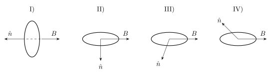
›Reveal solutionSolution
Use U=−mBcosθ: energy falls monotonically as the angle between n^ and B shrinks from 180∘ to 0∘. Ranking the four pictures by that angle gives I, IV, II, III — option (C).
The concept first
A current loop of area A carrying current I behaves like a tiny bar magnet with magnetic moment
m=IAn^,
where n^ is the unit normal fixed by the right-hand rule from the current sense. In an external field the loop stores orientational potential energy
U=−m⋅B=−mBcosθ.
Why the minus sign? Because a magnet wants to line up with the field. Aligned (θ=0) is the state of lowest energy, U=−mB — stable equilibrium. Anti-aligned (θ=180∘) is the state of highest energy, U=+mB — unstable equilibrium (nudge it and it flips). Perpendicular is exactly halfway: U=0, and this is where the torque τ=mBsinθ is largest.
The key monotonic fact: as θ decreases from 180∘ to 0∘, cosθ increases, so U=−mBcosθ decreases steadily. Ranking energy is therefore just ranking the angle θ, from biggest to smallest.
Step-by-step
1. Orientation I. n^ points left, B points right — they lie on the same line, opposite senses: θ=180∘.
UI=−mBcos180∘=+mB(maximum possible).
2. Orientation IV. n^ points up-and-to-the-left while B points right — an obtuse angle (between 90∘ and 180∘). So cosθ<0 and
0<UIV<mB.
It sits below I but above the perpendicular case. …
- TG EAPCET 2022Set eng-2022-07-18-AN1 markMCQQ.Assertion (A) : The magnetic field lines are continuous and form closed loops. Reason (R) : Magnetic monopole does not exist. The correct option among the following is (A) (A) is true, (R) is true and (R) is the correct explanation for (A) (B) (A) is true, (R) is true but (R) is not the correct explanation for (A) (C) (A) is true but (R) is false (D) (A) is false but (R) is true
›Reveal solutionSolution
Both statements are true, and the non-existence of magnetic monopoles is the direct cause of the closed-loop nature of magnetic field lines (Gauss's law for magnetism). Option (A).
The concept first
Compare the two fields:
- Electric field. Charges come singly. A field line starts on a positive charge and ends on a negative one, so Gauss's law reads ∮E⋅dS=ε0qenc — a net flux exists whenever a charge is enclosed.
- Magnetic field. Despite long searches, an isolated magnetic pole has never been observed. Cut a bar magnet in half and each piece is again a complete dipole with its own N and S. Consequently Gauss's law for magnetism is
∮SB⋅dS=0(equivalently ∇⋅B=0)
for every closed surface.
Step-by-step
- Is the Reason true? Yes — no magnetic monopole has ever been detected; magnetic sources are always dipoles (current loops or spins). (R) is true.
- Is the Assertion true? Yes. Whatever magnetic field lines you draw — around a bar magnet, a solenoid, a straight current-carrying wire — they never terminate. Outside a bar magnet they run N → S; inside the magnet they continue S → N, completing the loop. Around a wire they are perfect circles. (A) is true. …
🎓Unlock everything free for 14 days
- ✓Full step-by-step solutions
- ✓Concept-first explanations
- ✓Methods, shortcuts & mistakes
- ✓PYQ mapping + timed mock tests
Full access for 14 days. No credit card required.