Q.A 3.0 cm wire carrying a current of 10 A is placed inside a solenoid perpendicular to its axis. The magnetic field inside the solenoid is given to be 0.27 T. What is the magnetic force on the wire?
🔒You're viewing a preview — the full solution, concept, methods & PYQ mapping are locked.
🔒 Start your 14-day free trial to unlock the full solution →Concept understanding — Magnetic Force on Current
Magnetic Force on Current
Imagine a garden hose spraying pure water — bring a magnet near the stream and nothing happens, because water is electrically neutral. But if that stream carried electric charge (a current), the magnet would push the whole stream sideways. That is the essence of this concept: a current-carrying wire placed in a magnetic field experiences a sideways force, because every moving charge inside the wire feels the Lorentz force, and since the charges cannot leave the wire, they drag the wire along with them.
From a single charge to a wire
A single charge q moving with velocity v in a field B feels F=q(v×B). A current is just many such charges drifting together, so summing their individual forces over the whole wire gives a net force on it.
The metal lattice itself is neutral and stationary — only the free electrons drift. The magnetic force acts on those drifting electrons, which then collide with the lattice and transfer the push to the entire wire.
The formula
For a straight wire of length L carrying current I in a uniform field B:
F=I(L×B),F=ILBsinθ
where L points along the current and θ is the angle between the wire and B.
The force is zero when the wire runs parallel to the field (θ=0∘ or 180∘) and maximum when perpendicular (θ=90∘) — the magnetic force only responds to the component of current motion that is perpendicular to B.
Direction: the right-hand rule
Point your index finger along the current (L), your middle finger along the field (B); your thumb then gives the force direction — this is just the cross product L×B read off by hand. Because it is a cross product, swapping the two vectors reverses the force.
Worked example
A 0.5 m wire carries 3 A from east to west, in a uniform field of 0.2 T pointing north.
- θ=90∘ (the wire and the field are perpendicular), so F=ILBsinθ=(3)(0.5)(0.2)(1)=0.3 N. …
The key idea is that a current-carrying conductor in a uniform magnetic field experiences a force given by F=ILBsinθ, where θ is the angle between the current direction and the field.
Step 1: The wire is perpendicular to the solenoid’s axis, and the magnetic field inside a solenoid is along its axis. So the angle between the current and the field is θ=90∘, and sin90∘=1. …
The magnetic force on a current-carrying wire in a uniform field is given by F=ILBsinθ. Here the wire is perpendicular to the field (θ=90∘), so F=ILB. Substituting I=10 A, L=0.030 m, B=0.27 T gives F=0.081 N.
The Core Idea: Magnetic Force on a Current-Carrying Wire
When a current flows through a wire placed in a magnetic field, the moving charges experience a Lorentz force. For a straight wire of length L carrying current I in a uniform magnetic field B, the magnitude of the force is:
F=ILBsinθ
where θ is the angle between the direction of the current and the magnetic field vector. The direction of the force is given by Fleming's left-hand rule (or the cross product F=IL×B).
The key insight here is that the solenoid provides a uniform magnetic field along its axis. The wire is placed perpendicular to this axis, meaning the current direction is at 90∘ to the field. That makes sin90∘=1, so the force is simply F=ILB — no angular complication.
Step-by-Step Solution
1. Identify the given quantities
- Length of wire: L=3.0 cm=0.030 m (always convert to SI units)
- Current: I=10 A
- Magnetic field inside solenoid: B=0.27 T
- Angle between wire and field: θ=90∘ (since wire is perpendicular to solenoid axis, and the field is along the axis)
2. Write the formula for magnetic force
F=ILBsinθ
This is the standard expression derived from the Lorentz force law. The sinθ factor accounts for the component of the current that is perpendicular to the field — only that component experiences a force.
3. Substitute the values
Since sin90∘=1:
F=(10 A)×(0.030 m)×(0.27 T)×1
4. Calculate step by step …
Method: Magnetic Force on a Current-Carrying Wire (F = BIL sin θ)
This is a direct application of Lorentz force on a current-carrying conductor in a uniform magnetic field.
Steps
- Identify the formula The magnetic force on a straight current-carrying wire in a uniform field is:
F=BILsinθ
where:
- B = magnetic field strength (T)
- I = current (A)
- L = length of wire in the field (m)
- θ = angle between the wire and the magnetic field
-
Extract given data
- L=3.0 cm=0.030 m
- I=10 A
- B=0.27 T
- Wire is perpendicular to the solenoid's axis → θ=90∘
-
Apply the angle
sin90∘=1, so the formula simplifies to:
F=BIL
- Substitute and calculate
F=(0.27)(10)(0.030)
F=0.081 N
Final Answer …
Here are the common mistakes students make on this Magnetic Force Balance problem, along with how to avoid each.
Mistake 1: Using the wrong formula for magnetic force
Many students mistakenly use the force on a moving charge (F=qvB) or the force between two parallel wires, instead of the correct formula for a current-carrying conductor in a uniform field.
How to avoid:
Always identify the situation first. Here, a current-carrying wire is inside a uniform magnetic field (solenoid). The correct formula is:
F=BILsinθ
where:
- B = magnetic field (0.27 T)
- I = current (10 A)
- L = length of wire inside the field (not the whole wire length if partially inside)
- θ = angle between wire and field
Mistake 2: Forgetting to convert cm to metres
A very common slip: using L=3.0 directly without converting to SI units.
How to avoid:
Always convert centimetres to metres before plugging into F=BILsinθ.
L=3.0 cm=0.030 m
If you forget, your answer will be 100 times too large.
Mistake 3: Misidentifying the angle θ
Students often assume θ=90∘ is always correct, but sometimes the wire is parallel to the field (force = 0) or at some other angle.
How to avoid:
Read the problem carefully. Here: “perpendicular to its axis” means the wire is perpendicular to the solenoid’s magnetic field. So:
θ=90∘⇒sin90∘=1
If the wire were parallel, sin0∘=0 and force would be zero.
Mistake 4: Using the length of the solenoid instead of the wire
Some students take the length of the solenoid (e.g., 30 cm) as L, but the force acts only on the wire segment inside the field.
How to avoid:
The problem gives the wire length as 3.0 cm. That is the length inside the solenoid. Use that value (converted to metres).
--- …
Showing the 12 most recent of 20 on this concept.
- AP EAPCET 2026Set eng-2026-05-14-FN1 markMCQQ.If a current is passing in a spring, it (A) gets compressed (B) gets expanded (C) oscillates (D) remains unchanged
›Reveal solutionSolution
This tests the force between parallel current-carrying conductors, applied to the loops of a helical spring. Answer: it gets compressed.
Concept and Intuition
A spring carrying current is essentially a stack of closely-spaced current loops (like a solenoid). Two parallel wires carrying current in the same direction attract one another (this is the basic result behind the definition of the ampere). Since adjacent turns of the spring carry current flowing the same rotational way, neighbouring turns effectively attract each other, pulling the coils closer together.
Step-by-Step Solution
- Model the spring as a helix of closely-spaced circular current loops — locally, adjacent turns look like short parallel segments carrying current in the same direction.
- The magnetic force between two parallel currents flowing in the same direction is attractive (Ampère's force law).
- This attraction pulls each turn of the spring toward its neighbours. …
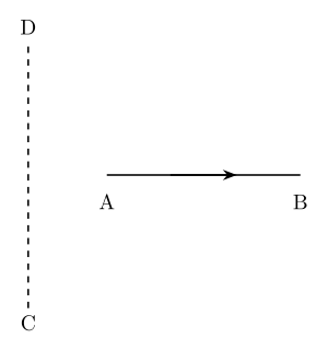
- AP EAPCET 2026Set eng-2026-05-15-AN1 markMCQQ.A current carrying wire AB is placed near an another long, straight current carrying wire CD as shown in figure. If AB is free to move, then AB will have [FIGURE: CD is a long straight vertical wire (dashed, current direction upward) and AB is a horizontal wire (current flowing from A to B, left to right) placed to the right of CD, oriented perpendicular to CD, with its left end A level with the midpoint of CD] (A) Translational motion only (B) Rotational motion only (C) Both translational and rotational motion (D) Neither translational nor rotational motion
›Reveal solutionSolution
The field from CD is non-uniform along AB, so the forces on different parts of AB are unequal in magnitude but parallel in direction — this produces both a net translation and a net torque; the answer is: both.
Concept and Intuition
Treating CD as an infinite straight wire, the magnetic field it produces at any external point in the plane containing the two wires is perpendicular to that plane, with magnitude B=2πrμ0I falling off with distance r from CD. Because AB is laid out along the direction of increasing r (A is closer to CD than B), the field is strongest near A and weakest near B. The force on each element of AB, dF=Idl×B, therefore points the same way everywhere along AB (perpendicular to AB, parallel to CD) — but its magnitude steadily decreases from A to B.
Step-by-Step Solution
- Because the field magnitude is unequal along AB (strong near A, weak near B) but always points the same way, integrating dF along the length of AB gives a non-zero net force — so AB translates. …
- AP EAPCET 2026Set ap-2026-05-20-AN1 markMCQQ.Two long parallel straight conductors separated by 10cm carrying currents 20A, 40A in the same direction. The work required per unit length to move the conductors apart to 30cm is [Take log103=0.4771] (A) 17.6×10⁻⁵ J m−1 (B) 21.2×10⁻⁵ Jm−1 (C) 16.8×10⁻⁵ Jm−1 (D) 14.6×10⁻⁵ Jm−1
›Reveal solutionSolution
The attractive force per unit length between parallel same-direction currents is μ0I1I2/2πd; integrating it from 10 cm to 30 cm gives the work done per unit length, about 17.6×10⁻⁵ J/m.
Concept and Intuition
Currents flowing in the same direction in two parallel wires attract each other. To pull them apart (increase their separation), an external agent must do positive work against this attractive force. Since the force is not constant with separation (f∝1/d), the work must be found by integrating force over distance, not by a simple F×Δd.
Step-by-Step Solution
- Force per unit length at separation d: f(d)=2πdμ0I1I2.
- Work done per unit length moving from d1=0.1 m to d2=0.3 m:
LW=∫0.10.3f(d)dd=2πμ0I1I2ln(d1d2)=2πμ0I1I2ln3
- 2πμ0=2×10⁻⁷; I1I2=20×40=800.
- ln3=2.303log103=2.303×0.4771=1.0989. …
- AP EAPCET 2025Set eng-2025-05-22-FN1 markMCQQ.The force per unit length on a straight wire carrying current of 8 A making an angle of 30° with a uniform magnetic field of 0.15 T is (A) 1.2 Nm−1 (B) 1.02 Nm−1 (C) 0.6 Nm−1 (D) 2.4 Nm−1
›Reveal solutionSolution
Force per unit length on a wire in a magnetic field is f=BIsinθ; plugging in the given values gives 0.6 Nm−1.
Concept and Intuition
A straight current-carrying wire of length L placed in a uniform magnetic field B experiences a force F=BILsinθ, where θ is the angle between the current direction and the field. This comes directly from the Lorentz force acting on the moving charge carriers, summed over the wire. Dividing both sides by L gives the force per unit length, f=BIsinθ — a useful quantity because it doesn't depend on how long the wire actually is.
Step-by-Step Solution
- Write the force-per-length formula: f=BIsinθ.
- Substitute B=0.15 T, I=8 A, θ=30°.
- sin30°=0.5.
- f=0.15×8×0.5=1.2×0.5=0.6 Nm−1.
Common Mistakes …
- AP EAPCET 2025Set ap-2025-05-19-FN1 markMCQQ.The magnetic force per unit length acting on a wire carrying a current of 43 A and making an angle of 60∘ with the direction of a uniform magnetic field of 200 mT is (A) 1.8 Nm−1 (B) 2.4 Nm−1 (C) 0.6 Nm−1 (D) 1.2 Nm−1
›Reveal solutionSolution
The force per unit length on a current-carrying wire in a magnetic field is F/L=BIsinθ; plugging in the given values yields 1.2N/m.
Concept and Intuition
A current-carrying conductor in an external magnetic field experiences a force F=IL×B, whose magnitude per unit length is F/L=BIsinθ, where θ is the angle between the current direction and the field.
Step-by-Step Solution
- Given I=43A, B=200mT=0.2T, θ=60∘.
- sin60∘=23.
- F/L=BIsinθ=0.2×43×23. …
- AP EAPCET 2024Set ap-2024-05-16-AN1 markMCQQ.A conducting rod of length 'l' and mass 'm' is placed over a smooth horizontal plane. A magnetic field B is acting perpendicular to the rod. If a charge 'q' is suddenly passed through the rod and the rod acquires an initial velocity v on the plane surface, then charge 'q' is (A) Blmv (B) vBlm (C) Bl2mv (D) mlBv
›Reveal solutionSolution
Equating the magnetic impulse (Bl times the total charge passed) to the rod's momentum change gives q=mv/(Bl).
Concept and Intuition
A current-carrying rod in a magnetic field experiences a force F=BIl. If the current is a brief, arbitrary pulse rather than constant, we cannot use F=ma directly with a single value, but the impulse (time-integral of force) is straightforward: J=∫Fdt=Bl∫Idt=Blq, since ∫Idt is exactly the total charge q that flowed.
Step-by-Step Solution
- Instantaneous force on the rod: F(t)=BI(t)l.
- Impulse (total change in momentum): J=∫0tFdt=Bl∫0tIdt=Blq.
- Since the rod starts at rest and ends with speed v: J=mv−0=mv. …
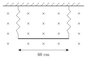
- AP EAPCET 2024Set ap-2024-05-16-FN1 markMCQQ.A wire of 60 cm length and mass 10 g is suspended by a pair of flexible leads in a magnetic field of 0.60 T as shown in the figure. The magnitude of the current required to remove the tension in the supporting leads is [FIGURE] (a horizontal wire of length 60 cm suspended by two vertical flexible leads inside a uniform magnetic field directed into the page, shown by rows of × symbols) (A) 0.47 A (B) 0.17 A (C) 0.27 A (D) 0.32 A
›Reveal solutionSolution
The key idea is that the magnetic force on the current-carrying wire must exactly balance its weight to remove tension in the leads. Using the formula F=ILB and setting it equal to mg, the required current is I=LBmg≈0.27 A, so the correct option is (C).
Concept and Intuition: Magnetic Force on a Current-Carrying Wire
When a wire carries an electric current and sits in a magnetic field, the field exerts a force on the moving charges inside the wire. This force is given by the simple but powerful equation:
F=IL×B
Here, I is the current, L is a vector pointing along the wire in the direction of the current (with magnitude equal to the wire's length), and B is the magnetic field. The magnitude of the force is F=ILBsinθ, where θ is the angle between the wire and the field.
In this problem, the wire is horizontal, and the magnetic field points directly into the page (shown by the "×" symbols). The wire is perpendicular to the field, so θ=90∘ and sinθ=1. The force is therefore F=ILB, and its direction is given by the right-hand rule: point your fingers in the direction of the current, curl them toward the field (into the page), and your thumb gives the force direction. For a current flowing left-to-right, the force points upward. That upward magnetic force can lift the wire, reducing the tension in the flexible leads. To remove the tension entirely, the magnetic force must exactly balance the wire's weight.
Step-by-Step Solution
- Identify the forces acting on the wire. The wire has weight mg pulling it downward. The flexible leads can only provide tension; if the magnetic force exactly cancels the weight, the leads go slack (tension = 0). So we require:
Fmagnetic=mg
- Write the magnetic force expression. Since the wire is perpendicular to the field, the magnitude is:
Fmagnetic=ILB
where L=60 cm=0.60 m, B=0.60 T, and I is the unknown current.
- Write the weight expression. Mass m=10 g=0.010 kg, and g=9.8 m/s2. So:
- AP EAPCET 2024Set ap-2024-05-17-AN1 markMCQQ.A very long straight conductor is carrying a steady current of 2.2 A. The conductor is placed on a horizontal table such that the current in the conductor is from south to north. If the horizontal component of the earth's magnetic field at the place is 3.2×10⁻⁵ T, the force per unit length on the conductor is (A) 7.04×10⁻⁵ T (B) Zero (C) 3.52×10⁻⁵ T (D) 14.08×10⁻⁵ T
›Reveal solutionSolution
The current flows exactly parallel to Earth's horizontal magnetic field (both south-to-north), so the magnetic force on it is zero.
Concept and Intuition
The force per unit length on a current-carrying wire in a magnetic field is LF=BIsinθ, where θ is the angle between the current direction and the field direction. Earth's horizontal magnetic field component at most places points from geographic south to geographic north (toward magnetic north, ignoring declination). If the wire's current also flows south to north, the current and field vectors are parallel — and a magnetic force requires a component of current perpendicular to the field, which is absent here.
Step-by-Step Solution
- Direction of current: south to north.
- Direction of Earth's horizontal field component: also south to north (that's the defining direction of the horizontal component).
- Angle between current and field: θ=0°. …
- AP EAPCET 2024Set eng-2024-05-21-FN1 markMCQQ.A rectangular loop of sides 25 cm and 10 cm carrying a current of 10 A is placed with its longer side parallel to a long straight conductor 10 cm apart carrying current 25 A. The net force on the loop is (A) 6.25×10⁻⁵ N (B) 5.5×10⁻⁵ N (C) 3.75×10⁻⁵ N (D) 8.75×10⁻¹¹ N
›Reveal solutionSolution
Only the two sides of the loop parallel to the wire feel a net (unbalanced) force since they're at different distances; the perpendicular sides' forces cancel by symmetry, leaving a clean two-term calculation.
Concept and Intuition
Two parallel current-carrying wires attract or repel with force per unit length 2πdμ0I1I2. For a rectangular loop near a long straight wire, the near and far sides parallel to the wire experience forces in opposite senses (because loop current flows in opposite directions along those two sides) but of different magnitude (since they're at different distances), so they don't cancel — their difference is the net force. The two sides perpendicular to the wire experience forces that are equal and opposite by symmetry (same current, mirror-image geometry along the wire's length) and cancel exactly.
Step-by-Step Solution
- Near side: 10 cm from wire, force per length =2πd1μ0I1I2.
- Far side: 10+10=20 cm from wire, force per length =2πd2μ0I1I2. …
- AP EAPCET 2023Set ap-2023-05-22-AN1 markMCQQ.A magnetic field of 1T is acting on a wire carrying current of 1A so that the wire is at rest in air. If the mass of the wire is 100 g then the length of the wire is (A) 1 m (B) 0.5 m (C) 2 m (D) 0.25 m
›Reveal solutionSolution
The magnetic force BIL on the current-carrying wire must equal its weight mg for it to float; solving for L gives about 1 m.
Concept and Intuition
A current-carrying wire in a magnetic field experiences a force F=BIL (for field perpendicular to the wire). If this force is directed upward and equals the wire's weight, the wire can remain suspended in equilibrium — a classic magnetic levitation setup.
Step-by-Step Solution
- Equilibrium condition: BIL=mg.
- m=100 g=0.1 kg, B=1 T, I=1 A, g≈9.8 ms−2. …
- AP EAPCET 2023Set eng-2023-05-16-FN1 markMCQQ.The force acting per unit length when a very long straight conductor is carrying a steady current of 1 A and the direction of the current is from south to north is (The horizontal component of the earth's magnetic field at the place is 3×10⁻⁵ T and the direction of the field is from the geographical south to geographical north.) (A) 3×10⁻⁵ Nm−1 (B) 1×10⁻⁵ Nm−1 (C) 0 (D) 1.5×10⁻⁵ Nm−1
›Reveal solutionSolution
This tests the force on a current-carrying conductor in a magnetic field, F=BILsinθ, when the current and field are parallel. Answer: the force is zero.
Concept and Intuition
The magnetic force per unit length on a straight current-carrying wire is f=BIsinθ, where θ is the angle between the current's direction and the magnetic field. This force vanishes whenever the current flows parallel (or antiparallel) to the field, because F=IL×B and the cross product of two parallel vectors is zero.
Step-by-Step Solution
- The conductor carries current from south to north.
- The Earth's horizontal magnetic field at the location also points from geographic south to geographic north. …
- AP EAPCET 2023Set eng-2023-05-17-AN1 markMCQQ.A wire loop of irregular shape carrying current is placed in an external magnetic field. If the wire is flexible, the shape of the loop changes to (A) helical (B) circular (C) straight line (D) parabolic
›Reveal solutionSolution
A flexible current loop free to move under the magnetic forces on it settles into a circular shape, since that shape balances the force per unit length uniformly all around.
Concept and Intuition
Each element of a current loop in a magnetic field feels a force dF=Idl×B. If the wire is rigid, its shape stays fixed and net force/torque may act on it as a whole. If instead the wire is flexible, each small segment can move independently in response to the local force on it, so the loop reshapes itself. The shape that gives a uniform, self-consistent outward force per unit length everywhere along the loop (mechanical equilibrium, like a stretched elastic band forced outward uniformly) is the circle — any irregular shape has regions of higher curvature that would keep deforming until the whole loop becomes circular.
Step-by-Step Solution
- Recognize that a flexible current loop is like an elastic ring being pushed outward (or inward) by magnetic forces at every point.
- The equilibrium shape under such uniformly-distributed radial forces is the one with constant curvature — a circle. …
🎓Unlock everything free for 14 days
- ✓Full step-by-step solutions
- ✓Concept-first explanations
- ✓Methods, shortcuts & mistakes
- ✓PYQ mapping + timed mock tests
Full access for 14 days. No credit card required.