Q.A closely wound solenoid 80 cm long has 5 layers of windings of 400 turns each. The diameter of the solenoid is 1.8 cm. If the current carried is 8.0 A, estimate the magnitude of B inside the solenoid near its centre.
🔒You're viewing a preview — the full solution, concept, methods & PYQ mapping are locked.
🔒 Start your 14-day free trial to unlock the full solution →Concept understanding — Magnetic Force Balance
Magnetic Force Balance
When a current-carrying wire or coil sits in a magnetic field, it feels a force F=BILsinθ (or, for a point charge, F=qvBsinθ). On its own that force just pushes the conductor - but in many real situations the push is deliberately set up to CANCEL another force, so the whole system sits in equilibrium. That equilibrium condition - magnetic force balanced against weight, against another wire's magnetic force, or against a mechanical counterweight - is what "magnetic force balance" means, and it is also historically how the ampere itself was defined.
The balance condition
Whenever a conductor is in equilibrium under a magnetic force and one other force, the two must be equal and opposite:
BILsinθ=Fother
Solving this equation for whichever quantity is unknown (B, I, L, or the other force) is the entire skill in this class of problem - the only new step, beyond the force law itself, is correctly identifying what the magnetic force is opposing.
Case 1: a wire suspended against gravity
A straight horizontal wire of mass m and length l, carrying current I, can be held up ("floated") in mid-air by a horizontal magnetic field perpendicular to it. The upward magnetic force must equal the downward weight:
BIl=mg⟹B=Ilmg
For example, a 200g, 1.5m wire carrying 2A needs B=(2)(1.5)(0.2)(9.8)≈0.65T to stay suspended.
Case 2: two wires balancing each other
Two long parallel wires carrying currents I1,I2 exert a force per unit length on each other of 2πdμ0I1I2 (attractive if the currents run the same way, repulsive if opposite). If one wire is free to move, this magnetic force can itself balance that wire's weight:
2πhμ0I2L=mg⟹h=2πmgμ0I2L
This is exactly how a "current balance" apparatus works, and historically it is how the ampere was defined: the current that, flowing in two infinite parallel wires one metre apart, produces a force of exactly 2×10⁻⁷N per metre of length.
Case 3: balancing on a beam
A current-carrying coil arm hanging from one pan of a beam balance feels an extra force F=NBIl when only that arm sits in an external field. Re-balancing the beam means adding a mass m so that mg=NBIl.
Always check which length enters the formula - for a coil of N turns the force multiplies by N; for a single suspended straight wire it doesn't. …
Why this formula?
Magnetic Force Balance: Why the Key Formulas Hold
The Magnetic Force Balance describes when the magnetic force on a charged particle or current-carrying conductor is exactly balanced by another force (gravity, electric force, or tension). Let's build the reasoning step-by-step.
1. The Core Idea: What Does "Balance" Mean?
A force balance means the net force on an object is zero:
Fnet=0
For magnetic forces we use the Lorentz force law:
- On a moving charge: Fm=q(v×B)
- On a current-carrying wire: Fm=I(L×B)
When this is balanced by another force (say gravity Fg=mg):
Fm+Fother=0
2. Case 1: Charged Particle in Crossed Fields (Velocity Selector)
A charged particle moves perpendicular to both electric field E and magnetic field B.
- Electric force: Fe=qE (along E)
- Magnetic force: Fm=q(v×B) (perpendicular to both v and B)
For straight-line motion (no deflection), the two forces must cancel:
qE=qvB⇒v=BE
Key insight: Only particles with this exact speed pass undeflected — this is how velocity selectors work in mass spectrometers.
3. Case 2: Current-Carrying Wire Balanced by Gravity
A horizontal wire carrying current I sits in a perpendicular magnetic field B, suspended by strings.
The magnetic force on a straight wire is Fm=ILBsinθ; for a wire perpendicular to the field (θ=90∘), Fm=ILB. Setting this equal to the weight Fg=mg for equilibrium:
ILB=mg
Key insight: This balance lets you measure B if I, L, and m are known — the principle behind a current balance experiment.
4. Case 3: Circular Motion of a Charged Particle …
Concept: Magnetic Field of a Finite Solenoid — For a long solenoid, the field near the centre is nearly uniform and given by B=μ0nI, where n is the total number of turns per unit length.
Step 1: Find total turns.
N=5×400=2000 turns.
Step 2: Find turns per unit length.
Length L=80 cm=0.80 m.
n=LN=0.802000=2500 turns/m.
Step 3: Apply formula.
B=μ0nI=(4π×10−7)×2500×8.0. …
The magnetic field inside a long solenoid is uniform and given by B=μ0nI, where n is the total number of turns per unit length. For this solenoid, n=2500 turns/m, so B≈2.5×10⁻² T.
The key insight here is that a solenoid’s magnetic field near its centre depends only on the total number of turns per unit length and the current — not on the number of layers or the wire diameter, as long as the solenoid is long compared to its radius. The field lines are nearly parallel and uniform inside, so we can use the ideal solenoid formula directly.
Let’s work through it step by step.
-
Find the total number of turns.
The solenoid has 5 layers, each with 400 turns.
Total turns N=5×400=2000 turns.
-
Find the length of the solenoid in metres.
Length L=80 cm=0.80 m.
-
Calculate the number of turns per unit length n.
n=LN=0.802000=2500 turns/m
- Apply the formula for the magnetic field inside a long solenoid. For an ideal solenoid (length >> radius), the field near the centre is:
B=μ0nI
where μ0=4π×10−7 T⋅m/A and I=8.0 A.
B=μ0nI
- Plug in the numbers.
B=(4π×10−7)×2500×8.0
First, 4π×10−7≈1.2566×10⁻⁶.
Then 2500×8.0=20000.
So B≈1.2566×10−6×20000=2.5132×10⁻² T.
Rounding to two significant figures (since the given data has two significant figures in current and length), we get: …
Method: Ideal Solenoid Approximation (Ampere's Law)
This method uses the fact that for a long, tightly wound solenoid, the magnetic field inside is nearly uniform and directed along the axis.
Steps
- Find the total number of turns The solenoid has 5 layers, each with 400 turns.
N=5×400=2000 turns
- Calculate the number of turns per unit length Length of solenoid, L=80 cm=0.80 m
n=LN=0.802000=2500 turns/m
- Apply the formula for B inside an ideal solenoid From Ampere's law, for a long solenoid:
B=μ0nI
where μ0=4π×10−7 T⋅m/A and I=8.0 A.
- Substitute and compute
B=(4π×10−7)×2500×8.0
B=4π×10−7×20000 …
Here are the common mistakes students make on this classic solenoid problem, along with how to avoid each.
1. Mistaking the total number of turns
The error:
Students often take N=400 (the turns per layer) instead of the total turns across all layers.
Why it happens:
The phrase “5 layers of windings of 400 turns each” is misread as “400 turns total.”
How to avoid:
Always multiply:
Ntotal=5×400=2000
Write it down explicitly before plugging into any formula.
2. Using the wrong length unit
The error:
Plugging L=80 directly into the formula without converting to metres.
Why it happens:
The formula B=μ0nI uses SI units — length must be in metres.
How to avoid:
Convert immediately:
L=80 cm=0.80 m
Then compute turns per metre:
n=LNtotal=0.802000=2500 turns/m
3. Confusing n (turns per metre) with N (total turns)
The error:
Using B=μ0NI instead of B=μ0nI.
Why it happens:
Memorising the formula without understanding that n is the density of turns.
How to avoid:
Remember:
B=μ0⋅(turns per unit length)⋅I
Always compute n=N/L first, then substitute.
4. Including the diameter in the calculation
The error:
Using the diameter 1.8 cm to find area or radius, then trying to use a formula like B=2Rμ0NI.
Why it happens:
Confusing a solenoid with a circular loop or a toroid.
How to avoid:
For an ideal solenoid (length >> diameter), the field inside is uniform and independent of the cross-sectional area. The diameter is a distractor here — ignore it unless the problem asks for flux.
5. Forgetting μ0 or using the wrong value
The error: …
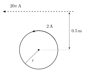
- AP EAPCET 2026Set eng-2026-05-14-AN1 markMCQQ.The radius of a coil of wire with N turns is 0.1 m and 2A current flows in the coil as shown. A long straight wire carrying a current of 20π A as shown is located at 0.5 m from the centre of the coil. The number of turns in the coil if the resultant magnetic field at the centre of the coil is zero [FIGURE: a circular coil of radius r carrying a current of 2A, with a current-direction arrow shown on the loop; a long straight wire is drawn above the coil (dashed line) carrying a current of 20π A shown flowing to the left, positioned at a perpendicular distance of 0.5 m from the coil's centre] (A) 2 (B) 4 (C) 6 (D) 10
›Reveal solutionSolution
This tests superposition of the magnetic field of a circular coil (at its centre) and of a long straight wire, set to cancel — solve for N by equating magnitudes.
Concept and Intuition
A circular coil of N turns carrying current I produces a field at its own centre of B=2rμ0NI, directed along the coil's axis (direction fixed by the right-hand rule for the shown current sense). A long straight wire carrying current I produces, at perpendicular distance d, a field B=2πdμ0I, circling the wire (again right-hand rule). The problem is engineered so that, given the current directions in the figure, these two fields point in opposite directions at the coil's centre. "Resultant field is zero" therefore just means the two magnitudes are equal — the geometry/direction part is already built into the problem statement, so we only need magnitude balance.
Step-by-Step Solution
- Field due to the coil at its centre: Bcoil=2rμ0NIcoil=2(0.1m)μ0N(2)=10μ0N. …
- AP EAPCET 2025Set eng-2025-05-21-AN1 markMCQQ.If a straight current carrying wire of linear density 0.12 kgm−1 is suspended in mid air by a uniform horizontal magnetic field of 0.5 T normal to the length of the wire, then the current through the wire is (Acceleration due to gravity =10 ms−2; Neglect earth's magnetic field) (A) 2.4 A (B) 1.2 A (C) 0.6 A (D) 4.8 A
›Reveal solutionSolution
A current-carrying wire floats in a horizontal magnetic field when the magnetic force exactly cancels gravity; solving gives I=2.4 A.
Concept and Intuition
A straight wire carrying current I in a magnetic field B (perpendicular to the wire) experiences a force per unit length F/L=BI. For the wire to be suspended in mid-air (in equilibrium), this magnetic force must balance the weight per unit length of the wire, which is λg where λ is the linear mass density.
Step-by-Step Solution
- Force balance per unit length: BI=λg.
- Solve for current: I=Bλg.
- Substitute values: λ=0.12 kg m−1, g=10 m s−2, B=0.5 T. …
- AP EAPCET 2022Set eng-2022-07-06-AN1 markMCQQ.Two infinitely long wires are placed at (1cm, 1cm) and (+1cm, -1cm) with 1A current in each and in the same directions perpendicular to x-y plane. Let the magnetic field due to these current carrying wires at the origin be B. If B0 is the magnitude of the field if only one of them was present, then B0∣B∣ is (A) 2 (B) 1 (C) 21 (D) 221
›Reveal solutionSolution
Two parallel wires symmetric about the x-axis add their fields at the origin constructively along one direction; the resultant is 2 times the field of either wire alone.
Concept and Intuition
An infinite straight wire carrying current I produces a field of magnitude μ0I/(2πd) at perpendicular distance d, circling the wire (direction given by z^×r^, where r^ points from the wire towards the field point, for current along +z^). With two wires we must add the two field vectors, not just their magnitudes.
Step-by-Step Solution
- Wire 1 is at (1,1) cm, wire 2 at (1,−1) cm; both distances from the origin are d=12+12=2 cm, so each alone gives a field of magnitude B0=2π2μ0I.
- Vector from wire 1 to origin: r1=(−1,−1). Field direction ∝z^×r1=(1,−1,0) (up to normalization).
- Vector from wire 2 to origin: r2=(−1,1). Field direction ∝z^×r2=(−1,−1,0). …
- AP EAPCET 2022Set eng-2022-07-06-FN1 markMCQQ.Two long parallel straight metal wires A and B carrying currents 12 A and 36 A respectively, in the same direction are separated by 50 cm. The point relative to A, where the resultant magnetic induction between the two wires due to the currents is zero, will be (A) 90 cm (B) 7.5 cm (C) 28 cm (D) 12.5 cm
›Reveal solutionSolution
With both currents in the same direction, the magnetic fields cancel only in the region between the two wires. Equating BA=BB and solving gives the null point at 12.5 cm from wire A (closer to the weaker current, as expected).
Concept and Intuition
Each long straight wire produces a field B=2πdμ0I circling around it. Between two wires carrying current in the same direction, the two fields point in opposite directions (one wire's field goes into the page there, the other's comes out), so they can cancel at some point between them. The cancellation point sits closer to the wire with the smaller current (since a weaker source needs to be closer to match the stronger one's field at the same magnitude).
Step-by-Step Solution
- Let the null point be at distance x from wire A, so it is at (50−x) cm from wire B.
- Equate the magnitudes: 2πxμ0(12)=2π(50−x)μ0(36).
- Cancel common factors: x12=50−x36. …
- AP EAPCET 2021Set eng-2021-10-05-FN1 markMCQQ.A tangent galvanometer has a coil of 50 turns and a radius of 20 cm. The horizontal component of earth's magnetic field is 3×10⁻⁵ T. What will be the current which gives a deflection of 45°? (A) 5π3 A (B) 3π5 A (C) 53π A (D) 35π A
›Reveal solutionSolution
At a 45° deflection the tangent law gives tan45°=1, so the coil's magnetic field exactly equals Earth's horizontal field, letting us solve directly for the current: I=5π3A.
Concept and Intuition
A tangent galvanometer balances the magnetic field of its coil against Earth's horizontal field H; the needle's deflection θ obeys tanθ=HBcoil, where Bcoil=2rμ0nI.
Step-by-Step Solution
- Tangent law: Bcoil=Htanθ. At θ=45°, tan45°=1, so Bcoil=H.
- Bcoil=2rμ0nI, so 2rμ0nI=H⇒I=μ0n2rH.
- Substitute r=0.2m, H=3×10⁻⁵T, n=50, μ0=4π×10−7: …
🎓Unlock everything free for 14 days
- ✓Full step-by-step solutions
- ✓Concept-first explanations
- ✓Methods, shortcuts & mistakes
- ✓PYQ mapping + timed mock tests
Full access for 14 days. No credit card required.