Q.Write the characteristics of a p-n junction which make it suitable for rectification.
A p-n junction acts as a rectifier because it conducts current strongly in forward bias (low resistance) and almost no current in reverse bias (very high resistance), effectively converting AC to DC.
Why a p-n junction works as a rectifier
Rectification means converting alternating current (AC) into direct current (DC). The key requirement is a device that allows current to flow in only one direction — like a one-way valve for electricity. A p-n junction does exactly this because of its asymmetric current-voltage (I-V) characteristic.
When you apply a forward bias (p-side positive, n-side negative), the depletion region narrows, the potential barrier drops, and majority carriers flow easily across the junction. The current is large and increases exponentially with voltage. In reverse bias (p-side negative, n-side positive), the depletion region widens, the barrier height increases, and only a tiny leakage current (due to minority carriers) flows — typically in the microampere range for silicon diodes.
This stark asymmetry — high forward current, negligible reverse current — is what makes the p-n junction suitable for rectification. Let's examine the specific characteristics that enable this.
The characteristics that enable rectification
1. Unidirectional conduction (asymmetric I-V characteristic)
The most fundamental property. In forward bias, the current grows exponentially with voltage:
where is the reverse saturation current, is electron charge, is Boltzmann's constant, is temperature, and is the ideality factor (typically 1–2). In reverse bias, the current saturates at (very small):
For a typical silicon diode, is on the order of nanoamperes, while forward current at 0.7 V can be tens of milliamperes — a ratio of or more. This enormous difference means the junction acts as a near-perfect switch: ON in forward bias, OFF in reverse bias.
A common mistake is to think the junction conducts equally well in both directions. It does not — the reverse current is typically a million times smaller than the forward current at normal operating voltages.
2. Low forward resistance, high reverse resistance
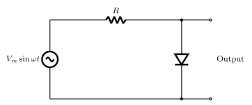
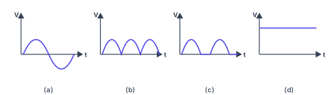
In forward bias, the dynamic resistance is small (typically a few ohms to tens of ohms). In reverse bias, the resistance is extremely high (megohms). This large resistance ratio — often or more — ensures that during the negative half-cycle of an AC input, almost no current flows, while during the positive half-cycle, current flows freely.
3. A well-defined threshold voltage (knee voltage)
For silicon, the forward current becomes significant only after the applied voltage exceeds about 0.7 V (the "knee" or "cut-in" voltage). For germanium, it's about 0.3 V. This threshold means the junction does not conduct for small forward voltages — but once crossed, conduction is strong. In rectifier circuits, this threshold causes a small voltage drop (the "forward voltage drop") in the output, which is acceptable for most applications.
For low-voltage rectification (e.g., 1–2 V AC), germanium diodes were historically preferred because of their lower knee voltage. Today, Schottky diodes (metal-semiconductor junctions) are used for even lower forward drops (~0.3 V) and faster switching.
4. Ability to withstand reverse voltage without breakdown (reverse breakdown voltage)
A rectifier must block reverse voltage without breaking down. The reverse breakdown voltage (typically 50–1000 V for power diodes) is the maximum reverse voltage the junction can withstand before avalanche or Zener breakdown occurs. For rectification, we operate well below this voltage. The junction's ability to hold off high reverse voltages without conducting is essential for handling the peak inverse voltage (PIV) in AC circuits.
For a half-wave rectifier, the PIV rating of the diode must exceed the peak AC voltage: .
5. Low reverse saturation current ()
The reverse saturation current is the tiny leakage current that flows when the junction is reverse biased. It arises from minority carriers thermally generated in the depletion region. For silicon, doubles roughly every C rise in temperature. A low (nanoamperes or less) ensures that the reverse current is negligible compared to the forward current, maintaining a high rectification efficiency.
6. Fast switching speed (for high-frequency rectification)
For AC mains (50/60 Hz), switching speed is not critical — ordinary p-n junction diodes work fine. But for high-frequency rectification (e.g., in switch-mode power supplies at kHz–MHz), the junction must turn off quickly. This depends on the minority carrier lifetime and junction capacitance. Fast recovery diodes (with gold doping or Schottky structures) have recovery times in nanoseconds, preventing excessive power loss during switching.
For standard 50 Hz mains rectification, the switching speed of a regular silicon diode (recovery time ~ microseconds) is more than adequate. The issue only arises at higher frequencies.
7. Thermal stability and power handling
A rectifier diode must dissipate the heat generated by forward current without exceeding its maximum junction temperature (typically C–C for silicon). The power dissipated is in forward bias. Good thermal conductivity and proper heat sinking ensure reliable operation. The junction's ability to handle this power without thermal runaway is a practical requirement for rectification.
Summary table of key characteristics
| Characteristic | What it means for rectification |
|---|---|
| Unidirectional conduction | Current flows only in forward bias |
| Low forward resistance | Small voltage drop when ON |
| High reverse resistance | Blocks current when OFF |
| Well-defined knee voltage | Predictable turn-on behaviour |
| High reverse breakdown voltage | Withstands peak inverse voltage |
| Low reverse saturation current | Minimal leakage when OFF |
| Adequate switching speed | Works at the required frequency |
| Thermal stability | Handles power dissipation safely |
The p-n junction is suitable for rectification because it conducts strongly in forward bias (low resistance) and blocks current almost completely in reverse bias (very high resistance), with a high reverse breakdown voltage and low reverse leakage current, enabling efficient conversion of AC to DC.
Unlock everything free for 14 days
- Full step-by-step solutions
- Concept-first explanations
- Methods, shortcuts & mistakes
- PYQ mapping + timed mock tests
Full access for 14 days. No credit card required.