Q.Explain with the help of a suitable diagram, the phenomenon on which an optical fibre works. Mention any two uses of optical fibres.
You're viewing a preview — the full solution, concept, methods & PYQ mapping are locked.
Start your 14-day free trial to unlock the full solution →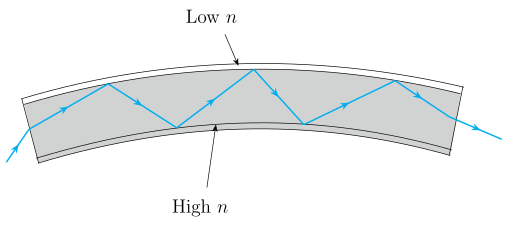
Optical fibres work on the principle of total internal reflection — light is trapped inside a thin glass/plastic core by repeated perfect reflections at the core-cladding boundary, allowing it to travel long distances with minimal loss. Two common uses: telecommunications (high-speed internet) and medical endoscopy (internal body imaging).
The Concept: Why Light Stays Inside a Fibre
The key idea is total internal reflection (TIR). When light travels from a denser medium (like glass) to a rarer medium (like air or a special cladding), it bends away from the normal. If the angle of incidence in the denser medium exceeds a certain critical angle (), the light cannot escape — it reflects back entirely into the denser medium, as if the boundary were a perfect mirror.
An optical fibre exploits this by having a core (high refractive index ) surrounded by a cladding (slightly lower refractive index ). Light launched into the core at a shallow enough angle will hit the core-cladding boundary at an angle greater than , and TIR keeps it bouncing down the fibre.
The critical angle is given by , where .
Step-by-Step Explanation
1. Structure of an optical fibre
A typical fibre has three layers:
- Core: A thin cylinder of glass or plastic (diameter ~8–50 μm for single-mode, ~50–100 μm for multi-mode). This is where light travels.
- Cladding: A layer of glass or plastic with a slightly lower refractive index. Its job is to ensure TIR occurs at the core-cladding interface.
- Buffer coating: A protective plastic jacket that shields the fibre from moisture and physical damage.
2. Launching light into the fibre
Light enters the fibre from a source (e.g., an LED or laser) at one end. For TIR to happen, the light must enter the core within a certain acceptance cone. The half-angle of this cone is called the acceptance angle (). If the incoming ray makes an angle greater than with the fibre axis, it will hit the core-cladding boundary at less than the critical angle and escape.
The numerical aperture (NA) of a fibre is (for air outside). A larger NA means the fibre accepts light from a wider cone — useful for coupling with LEDs, but it also allows more ray paths (modes), which can cause signal dispersion.
3. The journey inside: total internal reflection
Once inside, the ray strikes the core-cladding boundary. Because , and the angle of incidence is greater than , the ray reflects perfectly back into the core. It continues zigzagging down the fibre, losing very little energy — the cladding is essentially lossless for these reflections.
A common mistake is to think the cladding absorbs escaping light. In reality, TIR means no light enters the cladding at all — it's a perfect reflection. The cladding's role is to provide the lower refractive index and protect the core surface from scratches that would break TIR.
4. Diagram of the phenomenon …
Unlock everything free for 14 days
- Full step-by-step solutions
- Concept-first explanations
- Methods, shortcuts & mistakes
- PYQ mapping + timed mock tests
Full access for 14 days. No credit card required.