Q.(a) A parallel beam of light of wavelength 600 nm is incident normally on a slit of width 0.2 mm. If the resulting diffraction pattern is observed on a screen 1 m away, find the distance of
🔒You're viewing a preview — the full solution, concept, methods & PYQ mapping are locked.
🔒 Start your 14-day free trial to unlock the full solution →Part (a)Concept understanding — Single Slit Diffraction
Single Slit Diffraction: From Intuition to Precision
Imagine you're standing at the edge of a swimming pool and you send a straight wave toward a narrow gap in a wall. If the gap is wide, the wave mostly goes straight through — a clean "shadow" behind the wall. But if the gap is tiny, something strange happens: the wave spreads out in all directions beyond the gap, like ripples from a pebble. That spreading is diffraction.
Light does the same thing. When a parallel beam of light passes through a single narrow slit, it doesn't just make a sharp rectangle on a screen. Instead, you get a pattern: a bright central band, then dark bands (minima), then weaker bright bands (maxima), alternating as you move outward. The narrower the slit, the more the light spreads.
Why does this happen? The core idea
Light from every point across the slit travels to the screen. At any point on the screen, the light arriving from different parts of the slit has travelled different distances. If those path differences are exactly half a wavelength (λ/2), the waves cancel — you get darkness. If they are a whole wavelength (λ), they reinforce — you get a weaker bright band.
The key is that the slit is not a point source. It's a continuous line of sources, each sending out Huygens wavelets. The pattern is the result of interference among all those wavelets.
Common mistake
Students often think diffraction is just "bending around corners." That's part of it, but the real physics is interference between wavelets from different parts of the same slit. Without that interference, there would be no alternating dark and bright bands — just a fuzzy blur.
The precise condition for minima
Let the slit width be a and the wavelength be λ. For a point on a screen far away (the Fraunhofer or far-field condition), light rays from the slit are nearly parallel. The path difference between a wavelet from the top edge and one from the centre is 2asinθ, where θ is the angle from the straight-through direction.
For the first minimum, the wavelets from the top half of the slit cancel those from the bottom half exactly. That happens when the path difference between the two edges is exactly one wavelength:
asinθ=λ
For the second minimum, the slit can be divided into four equal zones, each cancelling the next, giving:
asinθ=2λ
In general, the condition for dark fringes (minima) is:
asinθ=mλfor m=±1,±2,±3,…
Notice m=0 is not a minimum — it's the centre of the bright central maximum.
What about the maxima?
The maxima occur roughly halfway between minima, but their positions are not given by a simple formula like asinθ=(m+21)λ. That formula works for double-slit interference, but for a single slit the maxima are slightly shifted. The exact positions come from solving a calculus problem (the derivative of the intensity function), but for exams you only need the minima condition and the fact that the central maximum is twice as wide as the others.
Quick exam fact
The angular width of the central maximum is 2θ1, where θ1 satisfies asinθ1=λ. So the central maximum spans from −λ/a to +λ/a in sinθ.
The intensity pattern (qualitative) …
Part (b)Concept understanding — Lens Maker's Formula
The Intuition: Why a Lens Bends Light
A lens works because light slows down when it enters glass. When a wavefront hits a curved surface at an angle, different parts of it slow down at different moments, and the wavefront bends. The stronger the curvature, the more it bends.
A lens has two surfaces. Each surface bends light by an amount that depends on its radius of curvature R and the refractive index n of the glass. The net bending — the focal length f — is the combined effect of both surfaces.
If you had a single spherical surface separating air from glass, its contribution to bending power is Rn−1. A lens has two such surfaces: light goes from air into glass at the first surface, then from glass back into air at the second. Because the two surfaces face opposite directions relative to the travelling light, their radii typically carry opposite signs.
This uses the New Cartesian Sign Convention (the one used in NCERT and CBSE): all distances are measured from the optical centre, and the direction the incident light travels in is taken as positive. So R is positive if the centre of curvature lies on the side the light is travelling towards (the outgoing side), and negative if it lies on the side the light is travelling from (the incident side).
The Precise Statement
For a thin lens (thickness negligible compared to the radii), the Lens Maker's Formula is:
f1=(n−1)(R11−R21)
where:
- f is the focal length of the lens (positive for converging, negative for diverging)
- n is the refractive index of the lens material relative to the surrounding medium (usually air)
- R1 is the radius of curvature of the first surface (the one light reaches first)
- R2 is the radius of curvature of the second surface
f1=(n−1)(R11−R21)
How to Apply It: A Worked Example
Take a biconvex lens made of glass (n=1.5) with both surfaces having the same radius of curvature magnitude, 20 cm.
Light travels left to right. The first surface bulges toward the incoming light, so its centre of curvature lies to the right of the surface — on the side the light is travelling towards. By the rule above, R1=+20 cm.
The second surface also bulges outward (away from the lens), so its centre of curvature lies to the left of that surface — on the side the light is travelling from. So R2=−20 cm.
Plug in:
f1=(1.5−1)(201−−201)=0.5×(201+201)=0.5×202=201
So f=+20 cm. Positive means converging — correct for a biconvex lens.
The most common mistake is getting the sign of R2 wrong. For a biconvex lens, R1 is positive and R2 is negative. For a biconcave lens, it's the reverse: R1 negative, R2 positive. Always sketch the lens and mark where each surface's centre of curvature actually sits.
Why the Formula Works (Brief Derivation) …
Part (a)
Given λ=600 nm=6×10⁻⁷ m, a=0.2 mm=2×10⁻⁴ m, D=1 m. Small angles: sinθ≈y/D.
- First minimum (asinθ=nλ, n=1):
y1=aλD=2×10−46×10−7×1=3×10⁻³ m=3 mm.
- Second (secondary) maximum — secondary maxima at asinθ=(n+21)λ; the second one is n=2, i.e. asinθ=25λ: …
Part (a): With λ=600 nm, a=0.2 mm, D=1 m: first minimum at 3 mm, second secondary maximum at 7.5 mm.
Part (b): For the equiconvex (μ1) + equiconcave (μ2>μ1) combination, P1/P2=−(μ1−1)/(μ2−1) and the net power P=2(μ1−μ2)/R<0, so the combination diverges.
Part (a)
For a single slit, minima occur at asinθ=nλ (n=1,2,…) and secondary maxima approximately at asinθ=(n+21)λ (n=1,2,…). With sinθ≈tanθ=y/D:
ymin=anλD,ymax≈a(n+21)λD.
Data: λ=6×10⁻⁷ m, a=2×10⁻⁴ m, D=1 m.
- First minimum (n=1):
y1=aλD=2×10−46×10−7×1=3×10⁻³ m=3 mm.
- Second maximum. The secondary maxima lie roughly midway between successive minima; the second secondary maximum is n=2 in (n+21)λ, i.e. 25λ: …
Showing the 12 most recent of 51 on this concept.
- CBSE 2026Set 55/1/11 markMCQQ.A concave lens of focal length 10 cm is cut into two identical plano-concave lenses. The focal length of each lens will be (A) 20 cm (B) 30 cm (C) 40 cm (D) 5 cm
›Reveal solutionSolution
Cutting a symmetric concave lens through its middle (perpendicular to the principal axis) leaves each piece with only one curved surface, so each plano-concave piece has half the power — and therefore double the focal length: 20 cm, option (A).
Concept and Intuition
The lens maker's formula relates a thin lens's focal length to its two radii of curvature and the refractive index of the material:
f1=(μ−1)(R11−R21)
A symmetric biconcave lens has two curved surfaces, and each contributes equally to the total power. When the lens is cut through its middle by a plane perpendicular to the principal axis, each piece keeps one original curved surface and gains a flat face. A flat surface has an infinite radius of curvature, so it contributes nothing to the power — each piece is left with only half the original bending power.
Step-by-Step Solution
1. Apply the formula to the original biconcave lens.
Use the New Cartesian sign convention with light travelling left to right. For a biconcave lens of equal radii of magnitude R: the first surface's centre of curvature lies on the incident (left) side, so R1=−R; the second surface's centre of curvature lies on the outgoing (right) side, so R2=+R. Then
f1=(μ−1)(−R1−+R1)=−R2(μ−1)
The negative sign confirms a diverging lens. With f=−10 cm:
Rμ−1=201 cm−1
2. Apply it to one plano-concave piece.
Each piece keeps one curved surface (R1=−R) and gains a flat cut face (R2=∞):
f′1=(μ−1)(−R1−∞1)=−Rμ−1=−201 cm−1
3. Read off the result.
f′=−20 cm …
- CBSE 2026Set 55/3/11 markMCQQ.A thin plano-convex lens and a thin equi-concave lens are kept coaxially in contact as shown in the figure. Assuming both the lenses are made of glass of refractive index μ, and R is the radius of curvature of each curved surface, the focal length of the combination is : (A) μ−1R (B) −μ−1R (C) μ−12R (D) −μ−12R
›Reveal solutionSolution
We calculate the focal lengths of the plano-convex and equi-concave lenses separately using the lens maker's formula, applying the correct sign conventions for radii of curvature. Then, we combine these focal lengths to find the equivalent focal length of the system. The focal length of the combination is −μ−1R.
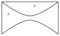
Figure — plano-convex and equi-concave lens combination Concept and Intuition
To find the focal length of a combination of thin lenses kept in contact, we first need to determine the focal length of each individual lens. The fundamental tool for this is the Lens Maker's Formula.
Lens Maker's Formula
The focal length f of a thin lens made of a material with refractive index μ (relative to the surrounding medium, usually air, for which μair=1) is given by:
f1=(μ−1)(R11−R21)
Here, R1 is the radius of curvature of the first surface encountered by light, and R2 is the radius of curvature of the second surface. The signs of R1 and R2 are crucial and follow a specific convention.
Sign Convention for Radii of Curvature
We will use the following convention for R1 and R2 in the lens maker's formula, assuming light travels from left to right:
- R1 (First Surface):
- If the first surface is convex (bulges towards the right), R1 is positive (+R).
- If the first surface is concave (bulges towards the left), R1 is negative (−R).
- If the first surface is flat (plano), R1 is infinite (∞).
- R2 (Second Surface):
- If the second surface is convex (bulges towards the left), R2 is negative (−R).
- If the second surface is concave (bulges towards the right), R2 is positive (+R).
- If the second surface is flat (plano), R2 is infinite (∞).
Watch outThe sign convention for R1 and R2 is a common source of error. Always be consistent with the convention you choose. The one outlined above ensures that converging lenses have positive focal lengths and diverging lenses have negative focal lengths when μ>1.
Combination of Thin Lenses in Contact
When two thin lenses with focal lengths f1 and f2 are placed coaxially in contact, the focal length F of the combination is given by:
F1=f11+f21
Step-by-step Solution
-
Identify the properties of the plano-convex lens (Lens 1).
- Refractive index: μ
- First surface: Flat. According to our sign convention, R1=∞.
- Second surface: Convex. It bulges towards the left (as seen from the second surface, or its center of curvature is to the left). According to our sign convention, R2=−R.
-
Calculate the focal length of the plano-convex lens (f1).
Using the lens maker's formula:
f11=(μ−1)(R11−R21)
Substitute the values for $R_1$ and $R_2$:f11=(μ−1)(∞1−−R1)
f11=(μ−1)(0+R1)
f11=Rμ−1
Therefore, the focal length of the plano-convex lens is:f1=μ−1R
This is a positive focal length, as expected for a converging lens.3. Identify the properties of the equi-concave lens (Lens 2).
* Refractive index: μ …
- R1 (First Surface):
- CBSE 2026Set V11 markQ.The bending of light around the corners and entering into the geometric shadow region is called __________. Fill in the blank choosing the appropriate answer from the bracket: (photons, diffraction, polarity, monopoles, greater than unity, less than unity)
›Reveal solutionSolution
- CBSE 2026Set ANNUAL1 markQ.Read the following passage carefully and answer the questions given below - Light entering in a dark room through a narrow gap under or around a closed door often appears to bend and spread. This is due to diffraction, the narrow gap acts like a slit, and light wave bends around the edges. This phenomenon is a small but clear demonstration of diffraction.(a) What would be the approximate size of sharp edge or opening compared to the wavelength of light for diffraction to be clearly observed?
›Reveal solutionSolution
Diffraction is prominent only when the aperture/obstacle size is comparable to the wavelength of light.
Diffraction effects become clearly noticeable only when the size of the slit/gap or obstacle is of the same order of magnitude as (comparable to) the wavelength of light used. If the opening is much larger than the wavelength, the bending is negligible and light appears to travel in straight lines (ray optics applies); as the opening size approaches the wavelength, diffraction (bending and spreading) becomes prominent — which is why the narrow …
- CBSE 2026Set ANNUAL1 markQ.Read the following passage carefully and answer the questions given below - Light entering in a dark room through a narrow gap under or around a closed door often appears to bend and spread. This is due to diffraction, the narrow gap acts like a slit, and light wave bends around the edges. This phenomenon is a small but clear demonstration of diffraction.(b) Why can the diffraction not be explained by ray-optics?
›Reveal solutionSolution
Ray optics assumes light always travels in straight lines and cannot describe the wave interference behind diffraction.
Ray (geometrical) optics treats light purely as straight-line rays and predicts that an obstacle or slit will simply produce sharp-edged shadows/beams, with no bending at the edges. Diffraction, however, is fundamentally a wave phenomenon — it arises from the superposition (interference) of secondary wavelets originating from different points of the same wavefront as it passes an edge or narrow opening (Huygens–Fresnel principle). Since ray optics ignores the wave nature of …
- CBSE 2026Set DS1 markQ.In which the power of a lens will be large — in air or water?
›Reveal solutionSolution
Power is larger in air, because the glass–water relative refractive index is smaller than the glass–air one.
Concept. By the lens-maker's formula the power of a lens depends on the refractive index of the lens relative to its surroundings:
P=f1=(mng−1)(R11−R21),
where mng=ng/nm is the index of glass with respect to the medium.
- In air (nm≈1): ang≈1.5, so (ang−1)≈0.5.
- In water (nm≈1.33): wng=1.5/1.33≈1.13, so (wng−1)≈0.13. …
- CBSE 2026Set ANNUAL1 markQ.Define diffraction of light.
›Reveal solutionSolution
Diffraction is the deviation of light from a straight-line path when it passes an obstacle or a narrow opening whose size is comparable to its wavelength.
Diffraction of light is the phenomenon of bending of light waves around the corners of an obstacle or spreading of light after passing through a narrow slit/aperture, so that light appears in regions that would be a dark geometrical shadow according to simple ray optics. It becomes noticeable when the size of the obstacle/aperture is comparable to the wavelength of light, and is a direct consequence of the wave nature of light (a manifestatio …
- CBSE 2026Set ANNUAL1 markMCQQ.The size of the obstacle for the diffraction of light should be(a) much larger than the wavelength of light(b) much smaller than the wavelength of light(c) of the order of wavelength of light(d) anything can happen
›Reveal solutionSolution
Diffraction (bending of waves around obstacles) is significant only when the obstacle or slit size is comparable to the wavelength - much bigger or much smaller sizes don't show it clearly.
Diffraction is the bending/spreading of waves as they pass an obstacle or through an aperture. This spreading is only prominent when the size of the obstacle/aperture (a) is of the SAME ORDER as the wavelength (lambda) of the wave, i.e. a ~ lambda. If the obstacle is much LARGER than the wavelength, the wave essentially travels in straight lines (geometrical shadow, negligible diffraction) - this is why we don't see visible light (wavelength ~500 nm) diffracting around everyday-s …
- CBSE 2026Set ANNUAL1 markQ.What do you understand by the term 'diffraction of light'?
›Reveal solutionSolution
Diffraction is the bending of light into the region that geometrical (ray) optics would call 'shadow' when it passes an obstacle or aperture.
According to simple ray/geometrical optics, light travelling past an obstacle or through a slit should produce a sharp-edged shadow. In reality, being a wave, light bends slightly around the edges of the obstacle/aperture and spreads into what would otherwise be the shadow region, producing a pattern of bright and dark fringes near the edges. This bending and spreading of light waves around obstacles/apertures is called diffraction. It becomes prominent only when the size of the obstacle or aperture is comparable to the wavelength of light, …
- CBSE 2026Set ANNUAL1 markMCQQ.Select the correct option with respect to the figures given below:(a) Fig.(i) depicts diffraction pattern and Fig.(ii) depicts interference pattern(b) Both depict interference pattern(c) Both depict diffraction pattern(d) Fig.(i) depicts an interference pattern due to a double-slit and Fig.(ii) depicts a diffraction pattern due to a single-slit
›Reveal solutionSolution
The key distinguishing feature between interference and diffraction intensity patterns is the relative heights of the fringes: interference from two narrow slits gives many fringes of roughly equal intensity, while diffraction from a single slit gives one strong central maximum with much weaker, rapidly falling secondary maxima.
Distinguishing interference from diffraction patterns
In Young's double-slit interference experiment, two coherent narrow sources produce a pattern of bright and dark fringes on the screen. Because the two slits are treated as (nearly) point/line sources of equal amplitude, the resulting bright fringes are all of comparable/roughly equal intensity across the region observed (there is a slowly-varying diffraction "envelope" from each slit's own finite width, but for the idealised interference pattern, the fringes near the centre appear as a series of similar-height peaks, evenly spaced by the fringe width β=λD/d).
In single-slit diffraction, light passing through one slit produces a pattern with:
- one very bright central maximum (roughly twice as wide as the secondary maxima), and
- a series of much fainter secondary maxima on either side, whose intensities fall off rapidly (roughly as 1/m2 or faster) with distance from the centre.
Applying this to the two figures
…
- CBSE 2026Set ANNUAL1 markQ.Write True or False: The energy redistribution takes place in phenomenon of diffraction.
›Reveal solutionSolution
True — diffraction redistributes light energy from minima to maxima; total energy is conserved.
Diffraction (like interference) does not create or destroy energy. Where destructive interference produces dark fringes (minima), the energy that would have arrived there is redistributed to the bright fringes (maxima), where constructive interference occurs. The average energy over the w …
- CBSE 2025Set 55/4/11 markMCQQ.Assertion (A): In a double slit experiment, if one slit is closed, the diffraction pattern due to the other slit will appear on the screen. Reason (R): For interference, at least two waves are required. (A) Both Assertion (A) and Reason (R) are true and Reason (R) is the correct explanation of the Assertion (A). (B) Both Assertion (A) and Reason (R) are true, but Reason (R) is not the correct explanation of the Assertion (A). (C) Assertion (A) is true, but Reason (R) is false. (D) Both Assertion (A) and Reason (R) are false.
›Reveal solutionSolution
The assertion is true — closing one slit leaves a single-slit diffraction pattern — and the reason is also true, because interference requires two coherent waves. But the reason does not explain the assertion; it merely states a necessary condition for interference, not why a single slit produces diffraction. So both are true, but (R) is not the correct explanation of (A). The correct option is (B).
Let’s unpack this carefully. The question tests your understanding of two distinct phenomena: diffraction and interference, and how they relate in a double-slit experiment.
1. What happens when both slits are open?
In the classic Young’s double-slit experiment, light from a single source passes through two narrow slits. Each slit acts as a coherent secondary source (Huygens’ principle). The waves from the two slits overlap on the screen and interfere — producing alternating bright and dark fringes (interference pattern). But that’s not the whole story.
Each slit individually also diffracts the light — because the slit width is comparable to the wavelength. So the actual pattern on the screen is a combination: a broad single-slit diffraction envelope modulating the sharp double-slit interference fringes.
The intensity in a double-slit experiment is:
I(θ)=I0(βsinβ)2cos2α
where β=λπasinθ (diffraction factor, a = slit width) and α=λπdsinθ (interference factor, d = slit separation).
2. Assertion (A): If one slit is closed, the diffraction pattern due to the other slit will appear.
Yes — this is true. When you block one slit, you are left with a single slit of width a. Light passing through that single slit spreads out due to diffraction. The pattern on the screen is a central bright maximum flanked by weaker, narrower secondary maxima — the classic single-slit diffraction pattern.
NoteThe single-slit diffraction pattern is given by I(θ)=I0(βsinβ)2, where β=λπasinθ. The first minimum occurs at sinθ=λ/a.
So the assertion is correct.
3. Reason (R): For interference, at least two waves are required.
This is also true. Interference is the superposition of two or more coherent waves. With one slit, you have only one wavefront emerging — so no interference between two separate sources. You get diffraction, not interference. …
🎓Unlock everything free for 14 days
- ✓Full step-by-step solutions
- ✓Concept-first explanations
- ✓Methods, shortcuts & mistakes
- ✓PYQ mapping + timed mock tests
Full access for 14 days. No credit card required.