Physics · Ch 9 — Ray Optics and Optical Instruments
The Microscope
The Microscope
Simple Microscope (Magnifier)
A simple microscope is just a converging lens of small focal length. It is held close to the object (at a distance less than or equal to the focal length) to produce an erect, virtual, and magnified image. The goal is to view this image comfortably, typically at the near point () or at infinity.
Case 1: Image at the Near Point ()
When the object is placed slightly inside the focal point, the virtual image forms at the near point. Using the lens formula with sign convention (, negative), the linear magnification is:
- : linear magnification (ratio of image height to object height)
- : near point distance (25 cm for normal eye)
- : focal length of the lens
Example: For , .
Case 2: Image at Infinity (Relaxed Eye)
If the object is exactly at the focal point (), the image forms at infinity. The eye is relaxed. The angular magnification is defined as the ratio of the angle subtended by the image () to the angle subtended by the object at the near point ():
- (angle subtended by image when object at )
- (angle subtended by object at near point)
This is one less than the near-point case, but viewing is more comfortable.
Compound Microscope
For higher magnification (beyond ), two lenses are used:
- Objective lens (near object): forms a real, inverted, magnified image.
- Eyepiece lens (near eye): acts as a simple magnifier on the first image.
The final image is inverted relative to the object.
Magnification by Objective
The linear magnification of the objective is:
- : tube length — distance between the second focal point of the objective and the first focal point of the eyepiece
- : focal length of the objective
Magnification by Eyepiece
- Final image at near point:
- Final image at infinity:
Total Magnification …
Drawn by us to help you understand the concept clearly, and verified to make sure it's accurate. For exams, practice from your NCERT textbook's own diagram.
What Fig. 9.23 Shows
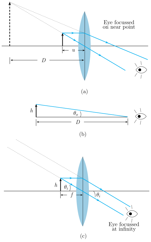
The figure has three panels (a), (b), and (c), each showing a single convex (converging) lens used as a simple magnifier. The lens has a small focal length , and its principal axis is drawn horizontally. The object (height ) is placed on the left side of the lens, and the eye is on the right side, close to the lens.
-
Panel (a): The object is placed just inside the focal point (i.e., at a distance from the lens). The lens forms an erect, magnified virtual image (height ) on the same side as the object. This image is located at the near point, a distance from the eye. Rays from the object are shown refracting through the lens; the virtual rays (dashed lines) extend backward to locate the image. The eye is drawn viewing this image comfortably.
-
Panel (b): This panel compares the angle subtended by the object at the near point without the lens (angle ) with the angle subtended by the image when viewed through the lens (angle ). The object is shown at the near point for the unaided eye, and the same object is shown placed closer to the lens for the aided view. The angles are drawn from the eye to the object/image.
-
Panel (c): The object is placed very close to the focal point (at ). The virtual image is now formed far away (closer to infinity than to the near point). The rays emerging from the lens are nearly parallel, indicating the image is at a large distance. The angle subtended by this image at the eye is small but still larger than for the unaided eye.
Labels include: object height , image height , focal point , near-point distance , the eye, the principal axis, and dashed virtual rays.
Physical Idea Taught
A simple magnifier allows you to bring an object closer to your eye than the near point (the closest distance for clear unaided vision, about 25 cm). By placing the object just inside the focal length of a convex lens, the lens produces an erect, magnified virtual image. The key is that the image is formed at a comfortable viewing distance (either at or at infinity), while the object itself is much closer to the lens. This increases the angle subtended at the eye, making the object appear larger.
- Image at the near point (panel a): The object is placed at a distance such that the virtual image is at . This gives the maximum linear magnification for a given lens, but viewing may cause some eye strain.
- Image at infinity (panel c): The object is placed exactly at the focal point (). The emerging rays are parallel, so the eye sees the image as if from infinity — this is the most relaxed viewing condition. The angular magnification is slightly less than in the near-point case, but the difference is small.
Key Formulas Developed from This Figure
- Linear magnification when the image is at the near point (): Using the lens formula and the sign convention ( negative, negative), the magnification becomes
Here is the near-point distance, and is the focal length of the lens. This is the ratio of image height to object height, and also equals the ratio of the angle subtended by the image to that subtended by the object when placed at .
- Angular magnification when the image is at infinity (): …
Drawn by us to help you understand the concept clearly, and verified to make sure it's accurate. For exams, practice from your NCERT textbook's own diagram.
What the Ray Diagram Shows
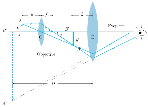
The figure presents a compound microscope as two converging lenses aligned on a horizontal axis. On the left is the objective lens (focal length ), and on the right is the eyepiece lens (focal length ). The object (a small upright arrow) is placed just beyond on the left side of the objective. The tube length is the distance between the second focal point of the objective and the first focal point of the eyepiece.
The Image Formation Process
-
Objective forms a real, inverted, magnified first image: Rays from the object pass through the objective. Because the object is just beyond , the objective produces a real, inverted, and enlarged image (the first image, shown as an inverted arrow) located near the first focal point of the eyepiece. The linear magnification of the objective is , where is the object height and is the height of the first image.
-
Eyepiece acts as a simple magnifier: The first image serves as the object for the eyepiece. This image is placed at (or just within) the focal plane of the eyepiece. The eyepiece then functions like a simple magnifier, producing a final virtual, enlarged, and inverted image (relative to the original object) that the eye sees. The ray diagram shows the final image at infinity (for relaxed viewing) or at the near point.
Key Formulas Derived from the Figure
The textbook uses the geometry of this ray diagram to derive the total magnification. The angle (shown in the figure) is the angle subtended by the first image at the eyepiece.
- Magnification by the objective: From the similar triangles formed by the object and the first image, the linear magnification is:
where is the tube length and is the focal length of the objective.
- Angular magnification by the eyepiece: When the final image is at infinity (relaxed eye viewing), the eyepiece acts as a simple magnifier with angular magnification:
where is the near point distance and is the focal length of the eyepiece. …