Electronics · Ch 6 — Oscillators
Crystal oscillator
Crystal oscillator
A crystal oscillator replaces the LC or RC tank with a vibrating quartz crystal, giving far higher frequency stability. It is the oscillator used wherever an accurate, fixed frequency is needed — communication sets, digital watches, clocks and calculators.
Principle: the piezoelectric effect
A crystal oscillator works on the piezoelectric effect. When an AC voltage is applied across a suitable crystal, the crystal vibrates mechanically at the frequency of the applied voltage; conversely, when the crystal is made to vibrate by a mechanical force, it develops an AC voltage across its faces.
The common piezoelectric substances are Quartz, Rochelle salt and Tourmaline. Rochelle salt shows the greatest piezoelectric effect (so it is preferred in microphones, headsets and loudspeakers) but is mechanically weakest, breaks easily and is affected by moisture and heat. Tourmaline shows the least piezoelectric effect but is mechanically strongest and most expensive. Quartz is a compromise — inexpensive, readily available in nature and mechanically robust — and is therefore the crystal commonly used in radio-frequency oscillators.
Circuit symbol of a crystal
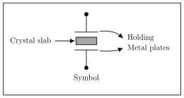
To use a crystal in an oscillator it is suitably cut and mounted between two metal plates. The circuit symbol (Figure 6.4.1) shows the crystal slab held between two metal plates, with leads brought out from the plates.
AC equivalent circuit of a crystal
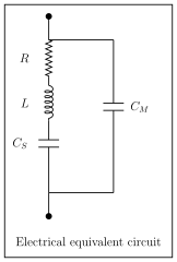
Electrically the crystal behaves like the network of Figure 6.4.2: a series branch of , and in parallel with a capacitance . In this model:
- is the electrical equivalent of the crystal's mass,
- is the electrical equivalent of its elasticity,
- is the electrical equivalent of its mechanical friction, and
- is the mounting capacitance formed by the two metal electrodes with the crystal slab as the dielectric.
When the crystal is not vibrating it behaves simply as the mounting capacitance . When it is vibrating it behaves as a tuned circuit. A crystal has two resonant frequencies — a series resonant frequency and a parallel resonant frequency — which lie very close together, and the value of is much smaller than . Its natural frequency is , where is a constant that depends on the way the crystal is cut and is the crystal's thickness — so the frequency is inversely proportional to thickness.
Series and parallel resonance
Series resonance. At one definite frequency the inductive and capacitive reactances of the series branch are equal, . The crystal then acts as a series resonant circuit of very low impedance, equal to . This frequency is the series resonant frequency
Parallel resonance. At a slightly higher frequency the net reactance of the series R-L- branch becomes inductive and equals the reactance of . The crystal then behaves as a parallel resonant circuit of very high impedance. This is the parallel resonant frequency
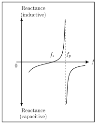
Since is smaller than , is always slightly greater than . The reactance-versus-frequency behaviour is sketched in Figure 6.4.3, with the reactance capacitive on either side and inductive in the narrow band between and . When the crystal is used in an oscillator, the oscillation frequency lies in this very narrow band between and .
The textbook writes the equivalent capacitance for two ways — as in the equivalent-circuit section and as in the parallel-resonance section. These are the same quantity: and simply stand for the crystal's own and . We use the labels consistently to match the equivalent circuit.
Circuit diagram of a crystal oscillator
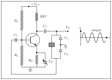
Figure 6.4.4 shows a BJT crystal oscillator. R1, R2 and RE provide the DC bias, CE is a bypass capacitor and CC provides coupling, while the RFC (radio-frequency choke) isolates the DC supply from the collector oscillations. The crystal is connected as a series element in the feedback path from collector to base, and it behaves like an inductor at a frequency slightly above its series resonance. It is therefore excited in the series-resonant mode. The transistor produces 180 degrees of phase shift and the capacitor voltage divider (C1, C2) a further 180 degrees, giving 360 degrees around the loop. The oscillation frequency equals the crystal's series resonant frequency,
…
A crystal oscillator uses a vibrating piezoelectric crystal to set the frequency. By the piezoelectric effect, an applied AC voltage makes the crystal vibrate at that frequency, and mechanical vibration of the crystal generates an AC voltage. Quartz, Rochelle salt and Tourmaline a …
Drawn by us to help you understand the concept clearly, and verified to make sure it's accurate. For exams, practice from your textbook's own diagram.
Figure 6.4.1 shows the circuit symbol of a crystal: a small shaded crystal slab sandwiched between two metal plates, with leads brought out from the plates. It represents the mounted cry …
Drawn by us to help you understand the concept clearly, and verified to make sure it's accurate. For exams, practice from your textbook's own diagram.
Figure 6.4.2 shows the AC equivalent circuit of a crystal: a series branch of R, L and Cs in parallel with a capacitance Cm. L represents the crystal mass, Cs its elasticity, R its mechanical friction and Cm the mounting capacitance. It grou …
At series resonance and the crystal has very low impedance (equal to R). The series resonant frequency is . Here L is the electrical equivalent of the crystal's mass and of its elasticity; is the frequency at which the crystal oscillator is excited, and being f …
At parallel resonance the crystal has very high impedance. The parallel resonant frequency is with . Since , is always slightly greater than . The crystal's natural frequency is inversel …
Drawn by us to help you understand the concept clearly, and verified to make sure it's accurate. For exams, practice from your textbook's own diagram.
Figure 6.4.3 sketches the crystal's reactance against frequency: capacitive (below the axis) on either side and inductive (above the axis) only in the narrow band between the series resonant frequency fs and the parallel resonant frequency fp (dashed asymptote). It shows why …
Drawn by us to help you understand the concept clearly, and verified to make sure it's accurate. For exams, practice from your textbook's own diagram.
Figure 6.4.4 is the BJT crystal oscillator: +Vcc, bias resistors R1, R2 and RE, bypass CE, coupling CC and an RFC to the collector, with the crystal as a series element in the collector-to-base feedback path and a C1-C2 capacitor divider. It grounds series-r …