Electronics · Ch 6 — Oscillators
Non sinusoidal Oscillator
Non sinusoidal Oscillator
So far every oscillator produced a sine wave. A non-sinusoidal oscillator produces a repeating output of some other shape, and the standard device for building one is the 555 timer. The 555 was first introduced in the early 1970s by Signetics Corporation as the SE/NE 555 timer. It is a monolithic timing IC that gives accurate and highly stable oscillations, is very reliable, easy to use and low in cost.
555 timer pin configuration
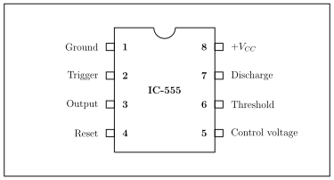
The 555 is available as an 8-pin metal can, an 8-pin mini DIP (dual-in-line package) or a 14-pin DIP. Internally the IC contains 23 transistors, 2 diodes and 16 resistors. Its eight pins (Figure 6.5.1) have the following functions:
- Pin 1 — Ground: the reference pin against which all voltages are measured.
- Pin 2 — Trigger: the trigger pulse is applied here; the output goes low when the trigger voltage is greater than one-third of Vcc.
- Pin 3 — Output: the timer output pin.
- Pin 4 — Reset: the timer is reset by a negative pulse at this pin; it should be tied to Vcc when not used, to avoid false triggering.
- Pin 5 — Control voltage: an external voltage applied here changes the internal threshold reference (normally two-thirds of Vcc).
- Pin 6 — Threshold: when the threshold voltage rises above the control-voltage level (two-thirds of Vcc), the output of comparator 1 goes high and the timer output goes low.
- Pin 7 — Discharge: the collector of the internal discharge transistor is connected here; it saturates or cuts off according to the state of the flip-flop.
- Pin 8 — +Vcc (Supply): the supply pin; the 555 works from +5 V to +18 V.
Block diagram of the 555 timer
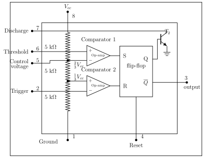
The functional block diagram (Figure 6.5.2) shows that a 555 timer contains two comparators, an RS flip-flop, an npn (discharge) transistor and three equal 5 kilo-ohm resistors. The three equal resistors form a voltage divider across the supply, fixing the comparator references at one-third and two-thirds of Vcc.
Working
When the threshold voltage exceeds the control voltage, comparator 1 sets the flip-flop, so its output goes high (). This high output saturates the discharge transistor T2 (turns the discharge path on), while the complementary output () sent to pin 3 keeps the output low. These conditions hold even if the threshold input later falls below two-thirds of Vcc — comparator 1 can only force the flip-flop high; it cannot change it back.
To change the output to low, the trigger input must fall below one-third of Vcc. Comparator 2 then triggers the flip-flop to the low state (), which turns the discharge transistor T2 off, and the output at pin 3 goes high ().
Bistable multivibrator …
The 555 timer is a low-cost monolithic timing IC (introduced by Signetics as the SE/NE 555) used to produce accurate, stable non-sinusoidal oscillations. It contains two comparators, an RS flip-flop, a discharge transistor and three 5 kilo-ohm resis …
| Pin | Name | Function |
|---|---|---|
| 1 | Ground | Reference pin for all voltage measurements |
| 2 | Trigger | Trigger pulse applied here; output goes low when trigger voltage > (1/3) Vcc |
| 3 | Output | Timer output pin |
| 4 | Reset | Reset by a negative pulse; tie to Vcc when unused to avoid false triggering |
| 5 | Control voltage | External voltage here changes the threshold reference (normally (2/3) Vcc) |
| 6 | Threshold | When threshold rises above (2/3) Vcc, comparator 1 goes high and output goes low |
Drawn by us to help you understand the concept clearly, and verified to make sure it's accurate. For exams, practice from your textbook's own diagram.
Figure 6.5.1 (Pin DIP) shows the 8-pin DIP 555 with the notch at top: left pins 1 Ground, 2 Trigger, 3 Output, 4 Reset; right pins 8 +Vcc, 7 Discharge, 6 Threshold, 5 Control voltage. It supports …
Drawn by us to help you understand the concept clearly, and verified to make sure it's accurate. For exams, practice from your textbook's own diagram.
Figure 6.5.2 is the 555 block diagram: three equal 5 kilo-ohm resistors form a divider setting comparator references at (1/3)Vcc and (2/3)Vcc; comparator 1 (threshold, pin 6) sets and comparator 2 (trigger, pin 2) resets an RS flip-flop whose output drives pin 3 and the discharge transist …
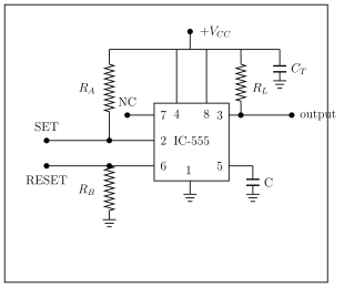
A bistable multivibrator has an output that is stable in both states; an external trigger switches it from one state to the other and it stays there until the next trigger, like a flip-flop. Built with a 555 it has no RC timing network: pulling the trigger to ground sets the output h …
Drawn by us to help you understand the concept clearly, and verified to make sure it's accurate. For exams, practice from your textbook's own diagram.
Figure 6.5.3 shows a 555-based bistable multivibrator: +Vcc, a pull-up resistor to the output, trigger (SET) and reset (RESET) inputs held high through pull-up resistors RA and RB, the threshold input grounded, and the output at pin 3. It illustrates t …