Electronics · Ch 6 — Oscillators
Oscillatory circuit or tank circuit
Oscillatory circuit or tank circuit
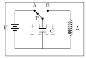
A circuit that produces electrical oscillations of any desired frequency is called an oscillatory circuit or tank circuit. The simplest tank circuit is a capacitor in parallel with an inductance coil , fed through a two-way plug key APB (Figure 6.2.1a).
How a tank circuit oscillates
Suppose the moving pole P of the key is first thrown to point A. The capacitor charges to the battery potential , the upper plate becoming positive and the lower plate negative — the tank now stores electrostatic energy in .
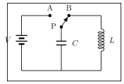
Now P is thrown to point B (Figure 6.2.1b). The inductor and capacitor form a closed loop and the capacitor begins to discharge through . Because the current is changing, the coil develops an induced emf that opposes the growth of current (Lenz's law), so the capacitor does not discharge instantly; instead the current rises gradually and builds a magnetic field around the coil. When the current is maximum the potential difference across the capacitor is zero — all the electrostatic energy of has been converted into magnetic energy stored in . Assuming no resistance, no energy is lost in this interchange.
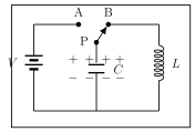
Once the capacitor is fully discharged the magnetic field starts to collapse and induces a counter-emf that, again by Lenz's law, keeps the current flowing in the same direction. This current recharges the capacitor with the opposite polarity — upper plate now negative, lower plate positive (Figure 6.2.1c). The capacitor then discharges again in the reverse direction, and the whole charge-discharge cycle repeats, producing an alternating (oscillating) current. The frequency of these oscillations is
Losses in the tank circuit
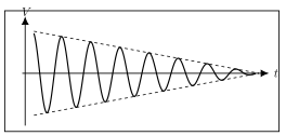
If there were truly no losses this energy interchange between and would continue forever. In a real tank circuit, however, there are resistive and radiation losses in the coil and dielectric losses in the capacitor, so a small part of the energy is lost every cycle. The amplitude therefore decreases steadily to zero, giving damped oscillations (Figure 6.2.2). To obtain sustained oscillations the lost energy must be replaced from outside — this is done by connecting an amplifier to the tank circuit, which is the basis of every LC oscillator.
LC oscillators
LC oscillators use inductance and capacitance to generate oscillations; each consists of an amplifier together with an LC tank circuit in its feedback network. According to the nature of the feedback there are two important types:
- Hartley oscillator — uses inductive feedback.
- Colpitts oscillator — uses capacitive feedback.
LC oscillators are widely used for high frequencies, in RF signal generators, radio and TV receivers and in high-frequency heating.
Hartley oscillator
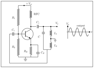
In the Hartley oscillator (Figure 6.2.3) the resistors R1, R2 and RE set the DC bias of the transistor, CE is a bypass capacitor and CC provides coupling. The RFC (radio-frequency choke) behaves as a short circuit for DC and an open circuit for AC, so it isolates the DC supply from the collector oscillations. Two inductors L1 and L2 (with a common tapping point) together with the capacitor form the tank circuit; the output is taken across L1.
Working. At switch-on the collector current charges , which then discharges through L1 and L2, setting up oscillations in the tank. The voltages developed across the two inductors are in opposite phase: the voltage across L2 is fed back to the input and the voltage across L1 is the output. The transistor amplifier provides 180 degrees and the tapped inductor another 180 degrees, giving 360 degrees around the loop, as required.
The frequency of oscillation is with the total tank inductance (if the mutual inductance between the coils is neglected; if it is present, , with for series-aiding and for series-opposition winding). The feedback ratio is
L1 and L2 are chosen so that , which fixes the required amplifier gain at (i.e. ).
Colpitts oscillator
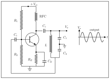
The Colpitts oscillator (Figure 6.2.4) has the same biasing arrangement — R1, R2 and RE for DC bias, CE as bypass, CC for coupling and the RFC for AC/DC isolation — but its tank circuit is a single inductor with two capacitors C1 and C2 in series, the junction between them being grounded.
Working. At switch-on the rising collector current charges C1 and C2. Because their common terminal is earthed, the voltages across the two capacitors are in opposite phase; the voltage across C2 is fed back to the amplifier. When the capacitors are fully charged they discharge through , sustaining the oscillation. The tank provides 180 degrees and the amplifier 180 degrees for a total of 360 degrees.
The voltage feedback fraction is
…
An oscillatory or tank circuit is a circuit that produces electrical oscillations of any desired frequency; its simplest form is an inductance coil L in parallel with a capacitor C. It oscillates by exchanging energy between the capacitor's electric field and the coil's magnetic field; real losses make this exchange decay, so an am …
Drawn by us to help you understand the concept clearly, and verified to make sure it's accurate. For exams, practice from your textbook's own diagram.
Figure 6.2.1a shows the tank circuit with battery V on the left feeding a two-way plug key (points A and B, pole P) into a capacitor C parallel with a coil L. With P at A the capacitor charges to V, upper plate positive. It sets up the st …
Drawn by us to help you understand the concept clearly, and verified to make sure it's accurate. For exams, practice from your textbook's own diagram.
Figure 6.2.1b shows the same tank with pole P thrown to B, so L and C form a closed loop and the capacitor discharges through the inductor, building a magnetic field in the coil. It illustrates the energy …
Drawn by us to help you understand the concept clearly, and verified to make sure it's accurate. For exams, practice from your textbook's own diagram.
Figure 6.2.1c shows the capacitor recharged with reversed polarity (upper plate negative, lower positive) after the collapsing magnetic field drives current on by Lenz's law. It completes one half of the oscillation cycle that …
The frequency of the oscillations produced by an LC tank circuit is , where L is the inductance and C the capacitance of the tank. Here f is in hertz when L is in henries and C in farads; the frequency rises as L or C is reduced, and this same expression sets the frequency of the Hart …
Drawn by us to help you understand the concept clearly, and verified to make sure it's accurate. For exams, practice from your textbook's own diagram.
Figure 6.2.2 shows the damped output of a practical tank circuit: a sine wave whose amplitude decays to zero (converging dashed envelope) because of coil resistance, radiation and dielectric losses. It motivates adding an amplifier to supply the lo …
An LC oscillator uses an inductor and capacitor to generate oscillations; it consists of an amplifier together with an LC tank circuit in its feedback network. The two important types are the Hartley (inductive feedback) and Colpitts (capacitive feedback) …
A Hartley oscillator is an LC oscillator using inductive feedback: its tank has two inductors L1 and L2 (tapped) with a capacitor C, the feedback voltage being taken acro …
Drawn by us to help you understand the concept clearly, and verified to make sure it's accurate. For exams, practice from your textbook's own diagram.
Figure 6.2.3 is the transistor Hartley oscillator: +Vcc feeds the collector through the RFC; R1, R2 and RE set the bias; CE bypasses RE; CC couples the output; the tank is two series inductors L1 and L2 (centre-tapped) in parallel with capacitor C, with the output taken across L1. It grou …
Frequency with (or when mutual inductance M is present: series-aiding, series-opposition). Feedback ratio ; with t …
A Colpitts oscillator is an LC oscillator using capacitive feedback: its tank has a single inductor L with two series capacitors C1 and C2 (their junction grounded), the feedbac …
Drawn by us to help you understand the concept clearly, and verified to make sure it's accurate. For exams, practice from your textbook's own diagram.
Figure 6.2.4 is the transistor Colpitts oscillator: +Vcc feeds the collector through the RFC; R1, R2 and RE bias the transistor; CE bypasses RE; CC couples the output; the tank is an inductor L in parallel with two series capacitors C1 and C2 whose common junction is grounded, feedback taken …
Frequency with equivalent tank capacitance . Feedback fraction ; with the requir …