Electronics · Ch 6 — Oscillators
RC Oscillators
RC Oscillators
RC oscillators use resistors and capacitors, instead of inductors, to generate low-frequency signals. The two important RC oscillators in the II PUC Electronics syllabus are the phase-shift oscillator and the Wein bridge oscillator.
Principle of phase shift in an RC circuit
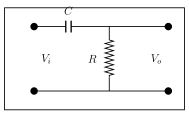
A phase-shift circuit is simply an RC network. One section (Figure 6.3.1a) has a series capacitor and a shunt resistor , with input applied and output taken across . When an AC voltage is applied, the voltage across leads the applied voltage by an angle , where
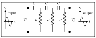
The value of depends on and : if then leads by 90 degrees (); if then . In practice is chosen so that each section gives a convenient lead. Three such RC sections in cascade (Figure 6.3.1b), each contributing 60 degrees, produce a total phase shift of 180 degrees, so the network output leads its input by 180 degrees.
Phase-shift oscillator
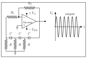
A phase-shift oscillator (Figure 6.3.2) uses an op-amp as the amplifying stage and three RC sections as the feedback network. The feedback network provides 180 degrees of phase shift and the op-amp inverting amplifier adds a further 180 degrees, so the loop phase shift is 360 degrees — the condition for positive feedback — and the circuit oscillates. Its frequency of oscillation is
At this frequency the required amplifier gain is and the feedback fraction is (so that ).
Principle of the lead-lag network
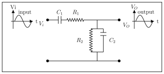
A lead-lag network is a circuit whose output voltage leads or lags the input voltage depending on frequency (Figure 6.3.3). It consists of a series combination of R1 and C1 followed by a parallel combination of R2 and C2. At low frequencies the series capacitor C1 behaves like an open circuit, so there is no output; at high frequencies the shunt capacitor C2 behaves like a short circuit, so again there is no output. At one particular frequency the output is a maximum, and when and ,
At low frequencies the phase angle is positive (the circuit leads), at high frequencies it is negative (the circuit lags), and at the frequency the phase angle is exactly zero. This zero-phase-shift, maximum-output condition is what the Wein bridge oscillator exploits.
Wein bridge oscillator
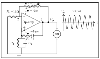
In the Wein bridge oscillator (Figure 6.3.4) a Wein bridge is connected between the amplifier's input and output terminals. One arm of the bridge is a series R1-C1 network, the adjoining arm is a parallel R2-C2 network, and the remaining two arms carry resistors R4 (= Ri) and R3 (= Rf). The phase criterion is that the total phase shift around the circuit must be 0 degrees, which happens only when the bridge is balanced — that is, at resonance. The frequency of oscillation is
The feedback (bridge) path produces no phase shift. The balance condition of the bridge is
which reduces to when the R's and C's are equal. The op-amp is used as a non-inverting amplifier, so its voltage gain is , the feedback fraction is , and the closed-loop gain is therefore .
Advantages, disadvantages, applications and limitations
Advantages of RC oscillators: (1) they need no inductors; (2) they can produce audio-range frequencies; (3) good frequency stability; (4) they can be used as variable-frequency oscillators; (5) the circuit is compact and less expensive. …
An RC oscillator uses resistors and capacitors (no inductor) to generate low-frequency signals. The two important types are the phase-shift oscillator and the Wein bridge oscillator. Because it needs no bulky inductor it is compact and inexpensive and suits the audio range; it selects its frequency using the frequency-dependent …
Drawn by us to help you understand the concept clearly, and verified to make sure it's accurate. For exams, practice from your textbook's own diagram.
Figure 6.3.1a shows a single RC section: a series capacitor C from input to output with a shunt resistor R to the common rail, input Vi on the left and output Vo across R. The voltage across R leads the applied volta …
For a single RC section the output across R leads the applied voltage by angle , where . If , ; if \ …
Drawn by us to help you understand the concept clearly, and verified to make sure it's accurate. For exams, practice from your textbook's own diagram.
Figure 6.3.1b shows three cascaded RC sections (three series capacitors C, three shunt resistors R), with input Vi' on the left and output Vo' on the right. Each section contributes 60 degrees, so the network shi …
A phase-shift oscillator uses an op-amp amplifier and three RC feedback sections: the RC network supplies 180 degrees and the inverting op-amp another 180 degrees, giving 360 degrees around t …
Drawn by us to help you understand the concept clearly, and verified to make sure it's accurate. For exams, practice from your textbook's own diagram.
Figure 6.3.2 is the phase-shift oscillator: an op-amp with feedback resistor Rf and input resistor Ri, and a feedback network of three RC sections returning the output to the input, each section adjusted for 60 degrees. It grounds the frequency f = 1/(2 …
Frequency . At this frequency the amplifier gain is and the feedback fraction is $\beta = \dfrac{ …
A lead-lag network is a circuit whose output leads the input at low frequencies and lags it at high frequencies; a series R1-C1 combination feeds a parallel R2-C2 combination. Its output is maximum with zero phase shift at one frequen …
Drawn by us to help you understand the concept clearly, and verified to make sure it's accurate. For exams, practice from your textbook's own diagram.
Figure 6.3.3 shows the lead-lag network: input Vi through a series C1-R1 combination to the output node, from which a parallel R2 and C2 branch goes to the common rail, output Vo taken across R2||C2. It grounds the maximum-outp …
When and , the lead-lag network gives maximum output with zero phase shift at ; the phase angle is positive (lead) below this freq …
A Wein bridge oscillator connects a Wein bridge (a series R1-C1 arm, a parallel R2-C2 arm and two resistor arms R3 = Rf, R4 = Ri) between an op-amp's input and output. It oscillates at the balance frequency, where t …
Drawn by us to help you understand the concept clearly, and verified to make sure it's accurate. For exams, practice from your textbook's own diagram.
Figure 6.3.4 is the Wein bridge oscillator: an op-amp with Rf and Ri, a series R1-C1 arm and a parallel R2-C2 arm forming the frequency-selective feedback, and a continuous sine output shown on a CRO. It grounds f = 1/(2pisqrt(R1C1R2* …
Frequency , reducing to when and . Bridge balance: (= 2 for equal components). Non-inverting gain , feedback …