Q.Biot-Savart law indicates that the moving electrons (velocity v) produce a magnetic field B such that
Concept understanding — Magnetic Force on Current
Magnetic Force on Current
Imagine a garden hose spraying pure water — bring a magnet near the stream and nothing happens, because water is electrically neutral. But if that stream carried electric charge (a current), the magnet would push the whole stream sideways. That is the essence of this concept: a current-carrying wire placed in a magnetic field experiences a sideways force, because every moving charge inside the wire feels the Lorentz force, and since the charges cannot leave the wire, they drag the wire along with them.
From a single charge to a wire
A single charge q moving with velocity v in a field B feels F=q(v×B). A current is just many such charges drifting together, so summing their individual forces over the whole wire gives a net force on it.
The metal lattice itself is neutral and stationary — only the free electrons drift. The magnetic force acts on those drifting electrons, which then collide with the lattice and transfer the push to the entire wire.
The formula
For a straight wire of length L carrying current I in a uniform field B:
F=I(L×B),F=ILBsinθ
where L points along the current and θ is the angle between the wire and B.
The force is zero when the wire runs parallel to the field (θ=0∘ or 180∘) and maximum when perpendicular (θ=90∘) — the magnetic force only responds to the component of current motion that is perpendicular to B.
Direction: the right-hand rule
Point your index finger along the current (L), your middle finger along the field (B); your thumb then gives the force direction — this is just the cross product L×B read off by hand. Because it is a cross product, swapping the two vectors reverses the force.
Worked example
A 0.5 m wire carries 3 A from east to west, in a uniform field of 0.2 T pointing north.
- θ=90∘ (the wire and the field are perpendicular), so F=ILBsinθ=(3)(0.5)(0.2)(1)=0.3 N.
- Direction: index finger west (current), middle finger north (field) — curling from west to north, the right-hand thumb points vertically downward. (Flip it: current flowing east with the same northward field gives a force straight up — reversing the current direction always reverses the force.)
For a wire that is not straight, in a uniform field the force still depends only on the net displacement vector from the start to the end of the wire, not on its actual curved path — a useful shortcut for irregular shapes.
Why it matters
This is the operating principle behind electric motors (opposite sides of a current loop feel opposite forces, producing rotation), galvanometers (a current-carrying coil deflects in a fixed field), and loudspeakers (a current-carrying voice coil is pushed back and forth by a magnet). It is not a new force — it is the same Lorentz force acting on the charges inside the wire, transmitted to the wire as a whole.
Queries like "force on current carrying conductor in magnetic field formula" and "moving charges and magnetism class 12 numericals" point to the Moving Charges and Magnetism chapter of the NCERT/CBSE Class 12 Physics curriculum. This same result underlies electric-motor and galvanometer questions commonly tested in JEE Main and NEET.
This is a Biot-Savart question about the FIELD a moving charge creates, not the force on it.
A charge q moving with velocity v produces, at a point whose position vector from the charge is r (unit vector r^), a magnetic field
B=4πμ0r2q(v×r^).
Because B comes from the cross product v×r^, it is perpendicular to both v and r. In particular B⊥v.
The magnetic field is perpendicular to the velocity, B⊥v (option a). Its magnitude falls off as 1/r2, not as an inverse cube.
The Biot-Savart field of a moving charge is B∝q(v×r^), so B is always perpendicular to the velocity v -- option (a), B⊥v.
What the question asks
It asks about the magnetic field a moving electron creates (the Biot-Savart law), not the force a field exerts on a current.
The Biot-Savart field of a moving charge
For a charge q moving with velocity v, the field at a point with position vector r (unit vector r^) from the charge is
B=4πμ0r2q(v×r^).
1. Direction. A cross product v×r^ is perpendicular to both vectors that build it. Hence B is perpendicular to v and to r. So B⊥v.
2. Magnitude. B=4πμ0r2qvsinθ, where θ is the angle between v and r. This is an inverse-square law in r, not inverse-cube.
3. Rejecting the other choices. B is not parallel to v (a cross product is never parallel to its factors), and it does not lie along the line joining the charge to the point (that line is r^, to which B is also perpendicular).
B⊥v -- the field is perpendicular to the electron's velocity (option a).
Method: Reading Off Field Direction/Magnitude Directly from the Biot-Savart Cross Product
For any "what does the Biot-Savart law say about the field of a moving/current-carrying source" question, the entire answer comes from the geometric properties of a cross product -- you rarely need to compute an actual number.
Steps
Step 1: Write the Biot-Savart field in cross-product form
For a moving point charge q (or a current element Idl), the field at a point displaced by r^ is:
B=4πμ0r2q(v×r^)(or dB=4πμ0r2Idl×r^)
Step 2: Use the cross-product rule to fix the direction
A cross product a×b is always perpendicular to both a and b -- never parallel to either, and never lying along a third, unrelated direction. So here B must be perpendicular to v (the source's velocity/current direction) and perpendicular to r^ (the line to the field point) simultaneously. This single fact eliminates "parallel to v" and "along the line joining source and point" options immediately.
Step 3: Use the 1/r2 prefactor to fix the distance dependence
The explicit r2 in the denominator makes this an inverse-square law, exactly like Coulomb's law for E -- never inverse-cube, inverse-linear, etc. Any option proposing a different power of r can be rejected on sight from the formula's structure.
Applying to this problem: with v as the electron's velocity, B⊥v follows immediately from Step 2 -- no vector algebra with actual numbers is needed to answer a qualitative direction/magnitude-dependence question like this one.
Showing the 12 most recent of 14 on this concept.
- COMEDK 2026Set 2026-A1 markMCQQ.A circular coil of radius r=10cm having 300 turns carries a current of 2 A . The coil is suspended vertically in a uniform magnetic field of strength 0.7 T . If the plane of the coil makes an angle 30∘ with the magnetic field, the torque needed to prevent it from turning is: (A) 11.42 Nm (B) 1.1 Nm (C) 22.84 Nm (D) 5.71 Nm
›Reveal solutionSolution
The torque on a current-carrying coil in a magnetic field is given by τ=NIABsinθ, where θ is the angle between the normal to the coil and the field. Here the plane makes 30∘ with the field, so the normal makes 60∘, giving τ≈11.42 Nm. The correct option is (A).
Concept & Intuition
A current loop in a magnetic field experiences a torque that tries to align its normal (the perpendicular to its plane) with the field. The formula is τ=NIABsinϕ, where ϕ is the angle between the normal and B.
The common pitfall: the problem gives the angle between the plane of the coil and the field, not the normal. If you use 30∘ directly, you get the wrong answer. Always convert: ϕ=90∘−(plane angle).
Step-by-step solution
-
Identify given quantities
- Radius r=10 cm=0.1 m
- Number of turns N=300
- Current I=2 A
- Magnetic field B=0.7 T
- Angle between plane of coil and B: θplane=30∘
-
Find the area of the coil
A=πr2=π(0.1)2=0.01π m2
- Determine the correct angle ϕ The torque formula uses the angle between the normal to the coil and B. Since the normal is perpendicular to the plane:
ϕ=90∘−θplane=90∘−30∘=60∘
- Apply the torque formula
τ=NIABsinϕ
Substitute values:
τ=300×2×(0.01π)×0.7×sin60∘
τ=300×2×0.01π×0.7×23
-
Simplify step by step
- 300×2=600
- 600×0.01=6
- So: τ=6×π×0.7×23
- 6×0.7=4.2
- τ=4.2×π×23=2.1π3
-
Numerical evaluation
π≈3.1416, 3≈1.732
τ≈2.1×3.1416×1.732≈2.1×5.441≈11.426 Nm
Rounded to two decimals: 11.42 Nm.
Watch outIf you mistakenly used sin30∘ instead of sin60∘, you would get τ≈6.60 Nm, which is not among the options — a clear sign you need the normal angle.
TipRemember: “plane angle” → subtract from 90∘; “normal angle” → use directly. A quick sketch of the coil and field lines saves errors.
✓Final answerThe correct option is (A).
ANSWER: A
-
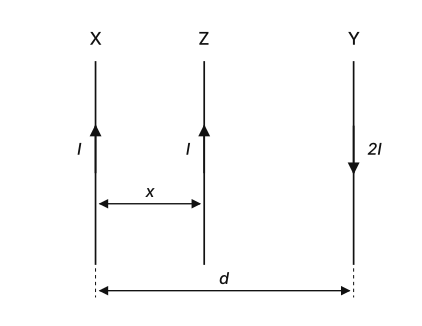
- COMEDK 2026Set 2026-M1 markMCQQ.Two long parallel conductors X and Y are placed vertically at a distance d apart. Conductor X carries a current I upwards and conductor Y carries a current 21 downwards. A third long conductor Z is placed parallel to both X and Y and between X and Y . If Z carries a current I upwards and is at a distance x from conductor X , then: A. All the conductors are in equilibrium and the net force on Z is zero B. The net force on Z is 2xπμ0I2[d−xd+x] towards X C. The net force on Z is 2xπμ0I2[d−xd+x] towards Y D. The net force on Z is 2xπμ0I2[d+xd−x] towards Y (A) B (B) D (C) A (D) C
›Reveal solutionSolution
Z (current I up) is attracted by X (current I up) and repelled by Y (current 2I down); both pushes point toward X, so they add. The net force is 2πxμ0I2[d−xd+x] towards X — that is statement B, which is choice (A).
Concept. Force per unit length between long parallel currents is F=2πrμ0I1I2: attractive for parallel currents, repulsive for antiparallel.
Step 1 — Force on Z from X. Both up (parallel) ⇒ attractive; separation x:
FZX=2πxμ0I⋅I=2πxμ0I2(toward X).
Step 2 — Force on Z from Y. Z up, Y down (antiparallel) ⇒ repulsive; Y is on the far side at distance d−x, so Z is pushed away from Y, i.e. also toward X:
FZY=2π(d−x)μ0I⋅2I=π(d−x)μ0I2(toward X).
Step 3 — Both forces point toward X, so they add.
Fnet=2πμ0I2(x1+d−x2)=2πμ0I2⋅x(d−x)(d−x)+2x=2πxμ0I2[d−xd+x],
directed towards X.
Step 4 — Match to statements. This magnitude with direction "towards X" is statement B. Statement A (equilibrium) is false, C has the wrong direction, D has the wrong expression. The choice naming statement B is (A).
✓Final answerNet force 2πxμ0I2[d−xd+x] towards X (statement B) — option (A).
ANSWER: A
- KCET 2025Set D-41 markMCQQ.A square loop of side 2m lies in the Y-Z plane in a region having a magnetic field B=(5i^+3j^−4k^)T. The magnitude of magnetic flux through the square loop is (A) 20Wb (B) 12Wb (C) 16Wb (D) 10Wb
›Reveal solutionSolution
Flux is the dot product B⋅A; the area vector of a Y–Z-plane loop is along i^, so only Bx survives.
Step 1 — The concept: magnetic flux is a dot product.
For a uniform field over a plane loop,
ΦB=B⋅A=BAcosθ
where A is the area vector — magnitude equal to the area, direction along the normal to the plane of the loop. The dot product is what picks out only the component of B that pierces the loop; a component lying in the plane of the loop threads nothing through it.
Step 2 — Find the area vector.
The loop lies in the Y–Z plane. The normal to the Y–Z plane is the x-direction, so
n^=i^
The side is 2m, so the area is
A=(2m)2=4m2⟹A=4i^ m2
Step 3 — Take the dot product.
B=(5i^+3j^−4k^) T
ΦB=B⋅A=(5i^+3j^−4k^)⋅(4i^)
Using i^⋅i^=1 and j^⋅i^=k^⋅i^=0:
ΦB=5×4=20 Wb
Step 4 — Sanity check on the discarded components.
The 3j^ and −4k^ parts of B lie inside the plane of the loop — they run parallel to its surface and pass through no part of it, so they contribute exactly zero flux. This is precisely why we must not use the magnitude ∣B∣=25+9+16=50 here; doing so would give ≈28.3Wb, which is not even an option — the question is deliberately checking that you take the component, not the magnitude.
The magnitude of the flux is therefore 20Wb.
✓Final answerThe correct option is (A) — 20Wb.
ANSWER: A
- COMEDK 2025Set 2025-A1 markMCQQ.A rectangular coil of length 10 cm and breadth 9 cm carries a current of 10 A . A long straight conductor carrying a current of 20 A is placed 1 cm from the coil parallel to its length and in the same plane of the coil. What will be the net force acting on the straight conductor? (A) 1.8×10⁻⁴ N (B) 3.6×10⁻⁴ N (C) 1.8×10⁻⁵ N (D) 3.6×10⁻⁵ N
›Reveal solutionSolution
The net force on the straight conductor is found by summing the magnetic forces from each side of the rectangular coil; due to symmetry, the forces from the two sides parallel to the conductor cancel, leaving only the force from the nearer perpendicular side, giving 3.6×10⁻⁴N.
Concept & Intuition
The problem involves two current-carrying conductors: a long straight wire and a rectangular coil. The force on a current-carrying conductor in a magnetic field is given by F=IL×B. Here, the magnetic field at the straight conductor is produced by the rectangular coil. Since the coil has four sides, each side contributes a magnetic field at the location of the straight wire. However, because the straight wire is parallel to the coil’s length and placed 1 cm away, the forces from the two long sides of the coil (parallel to the straight wire) will be equal in magnitude but opposite in direction — they cancel. The net force thus comes only from the two short sides (breadth) of the coil, but one is much farther away, so its contribution is negligible compared to the nearer one. We therefore compute the force due to the nearer breadth side.
Step-by-step solution
-
Set up the geometry and currents
Coil: length l=10cm=0.1m, breadth b=9cm=0.09m, current Ic=10A.
Straight conductor: current Is=20A, placed parallel to the coil’s length at a distance d=1cm=0.01m from the nearer side of the coil, in the same plane.
-
Identify which sides of the coil produce a net force
The straight conductor is parallel to the two long sides (length l). The magnetic field from a long straight wire at a distance r is B=2πrμ0I, directed tangentially. For the two long sides, the fields at the straight wire are equal in magnitude but opposite in direction (one attracts, one repels), so they cancel exactly.
The two short sides (breadth b) are perpendicular to the straight wire. The nearer short side is at distance d=0.01m; the farther short side is at distance d+l=0.11m. The force from the farther side is much smaller (by a factor of 11) and can be neglected for the net force calculation.
-
Compute the magnetic field at the straight wire due to the nearer short side
The short side is a straight wire of length b=0.09m carrying current Ic=10A. The straight conductor is at a perpendicular distance d=0.01m from the midpoint of this side? Actually, careful: The straight wire is placed 1 cm from the coil, parallel to the length. That means it runs alongside the coil, 1 cm away from the nearer long side. The short side is perpendicular to the straight wire, so the distance from the straight wire to the short side varies along the short side. However, since the straight wire is long and the short side is short, we can approximate the short side as a finite straight segment. The magnetic field at a point opposite the center of a finite wire of length b at perpendicular distance d is
B=4πdμ0I(sinθ1+sinθ2)
where θ1 and θ2 are the angles from the point to the ends of the wire. Here, the straight wire is parallel to the coil’s length, so it lies along the direction of the long side. The short side is perpendicular. The point on the straight wire closest to the short side is at the midpoint of the short side? Actually, the straight wire runs the entire length of the coil (10 cm) and beyond, so it is opposite the entire short side. The distance from the straight wire to the short side is constant = 1 cm? No — the straight wire is 1 cm from the long side, so the distance to the short side is also 1 cm at the corner, but varies. However, because the straight wire is long and the short side is short, the dominant contribution is from the segment of the straight wire directly opposite the short side. For simplicity, treat the short side as a long straight wire (since b≫d? Actually b=9 cm, d=1 cm, so b is 9 times d, so it's reasonably long). Use the formula for an infinite straight wire as an approximation:
B≈2πdμ0Ic
This is a good approximation because the short side is much longer than the distance.
So
B=2π×0.014π×10−7×10=0.012×10−6=2×10⁻⁴T
- Compute the force on the straight conductor The force on a length L of straight wire carrying current Is in a perpendicular magnetic field B is F=IsLB. But here, the magnetic field is not uniform along the entire straight wire — only the part opposite the short side experiences this field. The straight wire runs parallel to the coil’s length (10 cm), so the length of straight wire that is opposite the short side is exactly the breadth b=0.09m. So
F=Is×b×B=20×0.09×(2×10−4)=20×0.09×2×10−4
Compute: 20×0.09=1.8, then 1.8×2×10−4=3.6×10⁻⁴N.
- Check direction and net force The force from the nearer short side is attractive or repulsive depending on current directions, but magnitude is what we need. The farther short side contributes a much smaller force (distance 11 cm, field ~ 1.82×10⁻⁵ T, force ~ 3.27×10⁻⁵ N) but in the opposite direction, so the net is slightly less than 3.6×10⁻⁴ N. However, the options are spaced by factors of 10, so the dominant term gives the answer.
Watch outA common mistake is to include the forces from the two long sides — they cancel exactly, so don’t count them. Another pitfall is using the full length of the straight wire (10 cm) instead of the breadth (9 cm) for the force calculation; the field only acts over the segment opposite the short side.
TipWhen a long straight wire is parallel to one side of a rectangular coil, the forces from the two parallel sides cancel, and the net force is essentially due to the nearest perpendicular side. This simplifies many such problems.
✓Final answerThe correct option is (B).
ANSWER: B
-
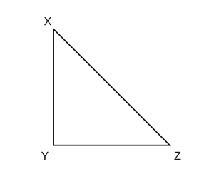
- COMEDK 2025Set 2025-E1 markMCQQ.A current carrying closed loop in the form of a right isosceles triangle XYZ is placed in a uniform magnetic field B acting along XY of the loop. If the magnetic force on the arm YZ is 2F, then the force on the arm XZ is: (A) −2F (B) 2F (C) +22F (D) −F
›Reveal solutionSolution
The net magnetic force on a current-carrying closed loop in a uniform field is always zero. Using the given force on YZ and the geometry of the right isosceles triangle, the force on XZ must be the negative of the vector sum of the forces on the other two sides, giving the answer as −2F, which is option (A).
Concept and Intuition
The key idea is a beautiful and powerful result: In a uniform magnetic field, the total magnetic force on any closed current-carrying loop is exactly zero. Why? Because the force on each infinitesimal current element is F=Idℓ×B, and when you integrate dℓ around a closed loop, you get the zero vector. So the vector sum of the forces on all three sides of the triangle must vanish:
FXY+FYZ+FXZ=0
We are told the force on YZ is 2F (presumably in some direction), and we need the force on XZ. If we can find the force on XY, we can solve for XZ. But the magnetic field is along XY — that gives us a huge shortcut.
Step-by-step reasoning
-
Identify the magnetic field direction.
The field B acts along XY. In the given figure, XY is vertical (from X at top-left to Y at bottom-left). So B points vertically downward (or upward — the exact sign doesn't matter for magnitude, but we must be consistent with vector directions).
-
Force on side XY.
The current in side XY flows along the same line as B (both along XY). The magnetic force on a current element is F=IL×B. If L and B are parallel (or antiparallel), their cross product is zero.
Therefore, the force on arm XY is zero: FXY=0.
-
Force on side YZ.
YZ is horizontal (from Y to Z). The field B is vertical. So LYZ is perpendicular to B. The magnitude of the force is FYZ=ILYZBsin90∘=ILYZB.
The problem states this force is 2F. So we have:
ILYZB=2F
The direction of this force is given by the right-hand rule: if current flows from Y to Z (say to the right) and B is downward, then FYZ points out of the page (or into it, depending on sign conventions). We don't need the exact direction for the magnitude, only that it is some vector we'll call FYZ.
- Force on side XZ (the hypotenuse). Since the net force on the loop is zero:
FXY+FYZ+FXZ=0
And FXY=0, so:
FXZ=−FYZ
That is, the force on XZ is exactly opposite in direction to the force on YZ, and has the same magnitude.
- Magnitude of force on XZ. The magnitude of FYZ is 2F, so the magnitude of FXZ is also 2F. But the question asks for the force on XZ, and the options include both positive and negative signs. The negative sign indicates the direction is opposite to that of the force on YZ. Hence, the force on XZ is −2F.
TipA common pitfall is to try to compute the force on the hypotenuse directly using ILBsinθ, which would give the same magnitude but requires careful geometry. The zero-net-force shortcut avoids all that — it’s faster and less error-prone.
Watch outSome students forget that the force on XY is zero because the current and field are parallel. If you mistakenly think XY also experiences a force, you’ll get the wrong vector sum.
✓Final answerThe correct option is (A).
ANSWER: A
-
- KCET 2024Set D-21 markMCQQ.A particle of specific charge mq=πCkg−1 is projected from the origin towards positive x-axis with the velocity 10 ms−1 in a uniform magnetic field B=−2k^ T. The velocity v particle after time t=121 s will be (in ms−1) (A) 5(i^+j^) (B) 5(i^+3j^) (C) 5(3i^−j^) (D) 5(3i^+j^)
›Reveal solutionSolution
A magnetic force does no work, so the speed stays 10 ms−1 and the velocity merely rotates through θ=ωt with ω=qB/m; find the sense of rotation from qv×B.
Step 1 — The concept: uniform circular motion
Since F=qv×B is always perpendicular to v, it does no work: the speed is constant and the velocity vector just rotates uniformly. Here v⊥B (velocity along x, field along −z), so the path is a full circle with angular frequency
ω=mqB=(mq)B
Step 2 — Compute the angular frequency
mq=π C kg−1,∣B∣=2 T
ω=π×2=2π rad s−1
(So the period is T=2π/ω=1 s — a neat check.)
Step 3 — Angle turned in the given time
θ=ωt=(2π)(121)=6π=30∘
(Equivalently: one-twelfth of a 1 s period is one-twelfth of a full circle =30∘.)
Step 4 — Which way does it turn?
Initially v=10i^ and B=−2k^. The magnetic force (taking q>0, as the positive specific charge implies) is
F=qv×B=q(10i^)×(−2k^)=−20q(i^×k^)
Since i^×k^=−j^:
F=−20q(−j^)=+20qj^
The force is along +j^, so the velocity is pulled from +x towards +y — an anticlockwise rotation in the x–y plane.
Step 5 — Write the velocity after 30∘
The speed remains 10 ms−1; rotate it anticlockwise by 30∘ from the +x axis:
v=10(cos30∘i^+sin30∘j^)
v=10(23i^+21j^)=53i^+5j^=5(3i^+j^) ms−1
Step 6 — Check the magnitude
∣v∣=53+1=5×2=10 ms−1 ✓
Speed is preserved, as it must be. (Option (C) has the same magnitude but rotates the wrong way; option (A) has magnitude 52 and option (B) is at 60∘, not 30∘.)
✓Final answerThe correct option is (D) — 5(3i^+j^).
ANSWER: D
- COMEDK 2024Set 2024-E1 markMCQQ.A wire of length 2 m carries a current of 1 A along the x axis. A magnetic field B=B0(i+j+k) tesla exists in space. The magnitude of magnetic force on the wire is (A) 2B0 N (B) Zero (C) 3B0 N (D) 22B0 N
›Reveal solutionSolution
The magnetic force on a current-carrying wire is given by F=IL×B. Here the wire lies along the x‑axis, so only the y‑ and z‑components of B contribute. The magnitude works out to 22B0 N, which corresponds to option (D).
Concept & Intuition
The force on a straight current-carrying wire in a uniform magnetic field is the cross product of the current direction (vector L) and the field B. Only the part of B perpendicular to the wire produces a force. Since the wire is along the x‑axis, the x‑component of B is parallel to the wire and contributes nothing. The y‑ and z‑components are perpendicular, so they combine to give a net force.
Step‑by‑step solution
-
Identify the given quantities
- Wire length: L=2 m along the x‑axis → L=2 i^ m
- Current: I=1 A
- Magnetic field: B=B0(i^+j^+k^) T
-
Write the magnetic force formula
For a straight wire in a uniform field:
F=I(L×B)
- Compute the cross product
L×B=(2i^)×(B0i^+B0j^+B0k^)
Using i^×i^=0, i^×j^=k^, i^×k^=−j^:
L×B=2B0(0+k^−j^)=2B0(−j^+k^)
- Multiply by current
F=1⋅2B0(−j^+k^)=2B0(−j^+k^) N
- Find the magnitude
∣F∣=2B0(−1)2+(1)2=2B02 N
TipA common mistake is to include the x‑component of B in the force calculation. Remember: the force from a magnetic field on a current element is always perpendicular to both the current direction and the field — so any field component parallel to the wire gives zero force.
Watch outDo not simply add the components of B as if they all contribute equally. The cross product picks out only the perpendicular parts.
✓Final answerThe correct option is (D).
ANSWER: D
-
- COMEDK 2023Set 2023-E1 markMCQQ.A circular loop of area 0.04 m2 carrying a current of 10 A is held with its plane perpendicular to a magnetic field induction 0.4 T Then the torque acting on the circular loop is : (A) 0.004 Nm (B) zero (C) 0.04 Nm (D) 0.02 Nm
›Reveal solutionSolution
The magnetic moment is along the loop's normal; with the plane ⊥B the moment is parallel to B, so τ=IABsin0=0.
The torque on a current-carrying loop in a magnetic field is
τ=m×B=IABsinθ
where θ is the angle between the magnetic dipole moment m (directed along the normal to the loop's plane) and B.
If the plane of the loop is perpendicular to B, then the normal (and hence m) is parallel to B, so θ=0 and
τ=IABsin0∘=0
✓Final answerThe correct option is (B) — zero
- COMEDK 2023Set 2023-M1 markMCQQ.A straight wire of length 2 m carries a current of 10 A. If this wire is placed in uniform magnetic field of 0.15 T making an angle of 45∘ with the magnetic field, the applied force on the wire will be (A) 1.5 N (B) 3 N (C) 32 N (D) 3/2 N
›Reveal solutionSolution
The magnetic force on the wire is F=BILsinθ=3/2 N.
The force on a current-carrying straight wire is
F=BILsinθ=(0.15)(10)(2)sin45∘.
=3×21=23 N≈2.12 N.
✓Final answerThe correct option is (D) — 3/2 N
- COMEDK 2022Set 20221 markMCQQ.A circular coil of 20 turns and radius 10 cm is placed in a uniform magnetic field of 0.10 T normal to the plane of the coil. If the current in the coil is 5 A, then the average force on each electron in the coil due to the magnetic field is (A) 2.5×10⁻²⁵ N (B) 4.5×10⁻²⁵ N (C) 5×10⁻²⁵ N (D) 5.5×10⁻²⁵ N
›Reveal solutionSolution
(Note the number of turns and the radius are not needed for this part - they only matter for the total torque/force, both of which are zero.)
Concept (NCERT problem): the magnetic force on a single electron is F = e v_d B, where v_d is the drift speed, obtained from I = n e A v_d. (Standard data used with this problem: n = 10^29 m^-3, wire cross-section A = 10^-5 m^2.)
Drift speed:
v_d = I / (n e A) = 5 / (10^29 x 1.6 x 10^-19 x 10^-5)
= 5 / (1.6 x 10^5) = 3.125 x 10^-5 m/s
Average force on each electron (velocity perpendicular to B):
F = e v_d B = (1.6 x 10^-19)(3.125 x 10^-5)(0.10)
= 5 x 10^-25 N
(Note the number of turns and the radius are not needed for this part - they only matter for the total torque/force, both of which are zero.)
✓Final answerThe correct option is (C) — 5×10⁻²⁵ N
ANSWER: C
- KCET 2021Set B-21 markMCQQ.A strong magnetic field is applied on a stationary electron. Then the electron (A) Moves in the direction of the field (B) Moves in an opposite direction of the field (C) Remains stationary (D) Starts spinning
›Reveal solutionSolution
The magnetic force F=q(v×B) is proportional to velocity; a charge at rest feels no magnetic force, however strong the field.
1. The concept — the Lorentz magnetic force.
A charge q moving with velocity v in a magnetic field B experiences
F=q(v×B),∣F∣=qvBsinθ
The crucial feature — and the whole point of the question — is that v appears inside the cross product. A magnetic field acts only on moving charges; it is fundamentally different from an electric field, which acts on a charge whether it moves or not (F=qE).
2. Apply it to a stationary electron.
v=0⟹F=q(0×B)=0
The field strength B multiplies zero — so however "strong" the field, the force is exactly zero.
3. Consequence.
By Newton's second law, a=F/m=0. With no acceleration and zero initial velocity, the electron simply remains at rest.
4. Why the other options fail.
- (A)/(B) A force along or opposite to B is impossible in any case: v×B is always perpendicular to B, so a magnetic field can never push a charge along its own direction.
- (D) "Starts spinning" — an external uniform field exerts no torque that sets a free point charge spinning; the electron's intrinsic spin is not something the field switches on.
✓Final answerThe correct option is (C) — Remains stationary.
ANSWER: C
- COMEDK 2021Set 2021-B1 markMCQQ.A wire carrying a current I is placed in the form of a curve y=αsin(Lπx), 0≤x≤2L. In the magnetic field of strength B. The force acting on the wire is [FIGURE: a sine curve y=αsin(πx/L) plotted over 0≤x≤2L, showing one full period (positive hump then negative hump) in a region of magnetic field B directed out of the plane (dots)] (A) IBL (B) πIBL (C) IBLπ (D) 2IBL
›Reveal solutionSolution
In a uniform field, F=ILeff×B where Leff is the straight line from start to end. Here that length is 2L, so F=2IBL.
For any shaped wire in a uniform magnetic field, the net force equals the force on the straight segment connecting its endpoints:
F=ILeff×B.
The curve y=αsin(πx/L) starts at x=0 (where y=0) and ends at x=2L (where y=αsin2π=0). The effective straight length is therefore 2L along the x-axis, perpendicular to B (out of the plane):
F=BI(2L)=2IBL.
✓Final answerThe correct option is (D) — 2IBL
🎓Unlock everything free for 14 days
- ✓Full step-by-step solutions
- ✓Concept-first explanations
- ✓Methods, shortcuts & mistakes
- ✓PYQ mapping + timed mock tests
Full access for 14 days. No credit card required.