Q.A galvanometer of resistance 10 Ω that gives maximum (full-scale) deflection for a current of 1 mA is to be converted into a multirange voltmeter reading 2 V, 20 V and 200 V. Three resistors R1, R2 and R3 are joined in series with the galvanometer, one after another. The 2 V terminal is tapped just after R1, the 20 V terminal after the series pair R1+R2, and the 200 V terminal after R1+R2+R3; each range terminal together with the common galvanometer terminal forms the two leads of the voltmeter for that range. Find R1, R2 and R3.
🔒You're viewing a preview — the full solution, concept, methods & PYQ mapping are locked.
🔒 Start your 14-day free trial to unlock the full solution →Concept understanding — Galvanometer to Voltmeter Conversion
Galvanometer to Voltmeter Conversion
A moving-coil galvanometer deflects fully only at a small current Ig (its full-scale deflection current) and has internal resistance G. To use it as a voltmeter — reading much larger voltages V — a large resistance Rs (the multiplier) is connected in series with the galvanometer coil. This series resistance limits the current to exactly Ig when the full-scale voltage V is applied, so the needle deflects fully and the scale is recalibrated to read volts instead of amperes.
The Conversion Formula
The galvanometer and Rs together form a series circuit of total resistance Rs+G. Applying V across this series combination drives a current
I=Rs+GV
We want this current to equal Ig exactly when V is the maximum (full-scale) voltage, so Ig=Rs+GV, which rearranges to:
Rs=IgV−G
Since the coil's deflection is proportional to the current through it, and that current is proportional to the applied voltage (Ohm's law), the resulting scale is linear in V: equal voltage steps give equal angular deflections.
Why series, not parallel?
A voltmeter must be connected across the component whose voltage is being measured, without diverting current away from it — so it should draw as little current as possible, meaning its own resistance must be as large as possible. Adding Rs in series does exactly that: it raises the meter's total resistance to Rs+G, which is deliberately made large. (This is the opposite requirement to an ammeter, which sits in the current path and needs the smallest possible resistance — achieved there with a small shunt in parallel, not a large resistor in series.)
Worked Example
For Ig=1 mA, G=50 Ω, converting to a 0–10 V voltmeter:
Rtotal=IgV=0.00110=10,000 Ω⟹Rs=10,000−50=9,950 Ω
A 9.95 kΩ resistor in series gives full-scale deflection at exactly 10 V.
Do not forget to subtract G from V/Ig. For most galvanometers G is small next to Rs, but in precision work it matters.
Key Properties
- High input resistance: Rv=Rs+G is large (kΩ to MΩ), so the voltmeter draws minimal current and barely disturbs the circuit it measures.
- Linear scale: deflection ∝ current ∝ voltage. …
A voltmeter reads V=Ig(G+Rseries) at full-scale. With Ig=1 mA and G=10 Ω, each higher range simply adds more series resistance. This gives R1=1990 Ω, R2=18 kΩ, R3=180 kΩ. …
To read a voltage V, a galvanometer must carry only its full-scale current Ig when that voltage is across the branch, so V=Ig(G+Rseries). Adding the three series resistors in turn raises the range from 2 V to 20 V to 200 V, giving R1=1990 Ω, R2=18 kΩ and R3=180 kΩ.
Concept & formula
A galvanometer becomes a voltmeter of range V by placing a large resistance R in series so that at the full-scale current Ig the total voltage drop equals V:
V=Ig(G+R).
Here G=10 Ω and Ig=1 mA=10−3 A, so Ig is common to every range and the resistance in the loop increases as R1, then R1+R2, then R1+R2+R3.
Step 1 — the 2 V range (galvanometer +R1)
2=Ig(G+R1)=10−3(10+R1) ⇒ 10+R1=2000 ⇒ R1=1990 Ω.
Step 2 — the 20 V range (galvanometer +R1+R2) …
Method: Designing a Multi-Range Voltmeter From a Single Galvanometer
General technique for any "convert this galvanometer into a voltmeter with ranges V1,V2,V3,…" problem, whether the resistors are separate branches or one series chain tapped at intermediate points.
Steps
Step 1: Write the governing equation for full-scale deflection
At full-scale the current through the galvanometer coil is always exactly Ig, and Ohm's law across the SERIES combination of the coil resistance G and whatever series resistance is in the current path gives:
V=Ig(G+Rseries)
Step 2: Identify what "series resistance" means for each range, from how the taps are wired
If the range terminals are taps along one resistor chain, the resistance in the loop for the n-th range is the SUM of every resistor up to that tap (R1, then R1+R2, then R1+R2+R3, …) — not just the newly added resistor alone.
Step 3: Solve the equations in order, from the smallest range up …
Showing the 12 most recent of 14 on this concept.
- COMEDK 2026Set 2026-A1 markMCQQ.A galvanometer of resistance 50Ω is having 30 divisions and a current sensitivity 10 mA/ div. What should be the shunt resistance so that it can be converted into an ammeter of range 10 A ? (A) 0.76Ω (B) 2.5Ω (C) 1.55Ω (D) 3.1Ω
›Reveal solutionSolution
The key idea is that a shunt resistor bypasses most of the current around the galvanometer. The full-scale deflection current of the galvanometer is 0.3 A, and to extend the range to 10 A, the shunt must carry the remaining 9.7 A. Using the parallel voltage equality, the required shunt resistance is approximately 0.0155 Ω, which corresponds to option (C).
Concept and Intuition
A galvanometer is a sensitive current-measuring device that deflects fully when a small current (here, 0.3 A) passes through it. To measure larger currents (like 10 A), we connect a shunt resistor in parallel with the galvanometer. The shunt "steals" most of the current, allowing only the safe, small current through the galvanometer. The trick is that the voltage across the galvanometer and the shunt must be equal (since they are in parallel). This voltage equality gives us the shunt resistance directly.
Step-by-Step Solution
- Find the full-scale deflection current of the galvanometer. The galvanometer has 30 divisions and a sensitivity of 10mA/div. So the current for full-scale deflection is:
Ig=30×10mA=300mA=0.3A.
- Determine the current that must flow through the shunt. The ammeter's total range is I=10A. When the galvanometer shows full deflection (0.3 A through it), the remaining current goes through the shunt:
Is=I−Ig=10−0.3=9.7A.
- Apply the parallel voltage condition. In a parallel circuit, voltage across the galvanometer equals voltage across the shunt:
- COMEDK 2026Set 2026-M1 markMCQQ.A 50Ω galvanometer is shunted by a resistance of SΩ. If 8% of total current passes through the galvanometer, the value of S is: (A) 4Ω (B) 4.35Ω (C) 3.9Ω (D) 3.35Ω
›Reveal solutionSolution
The shunt resistor is chosen so that only 8% of the total current flows through the galvanometer. Using the current-divider rule for parallel resistors, the shunt resistance is found to be approximately 4.35 Ω, which corresponds to option (B).
Concept & Intuition
A galvanometer is a sensitive current-measuring device that can only handle a small current. To measure larger currents, we connect a low-resistance shunt in parallel with it. The shunt diverts most of the current away from the galvanometer.
The key idea: In a parallel circuit, the current divides inversely with resistance. If only 8% of the total current goes through the galvanometer, then 92% goes through the shunt. The ratio of currents equals the inverse ratio of resistances.
Step-by-step solution
-
Define the currents
Let I be the total current entering the parallel combination.
Current through galvanometer: Ig=8% of I=0.08I
Current through shunt: Is=I−Ig=0.92I
-
Apply the parallel current-divider rule
For two resistors in parallel, the current through one branch is given by:
Ig=I×G+SS
where G=50 Ω is the galvanometer resistance and S is the shunt resistance.
(This formula works because the voltage across both is the same: IgG=IsS.)
- Substitute the known values
0.08I=I×50+SS
Cancel I (assuming I=0):
0.08=50+SS
- Solve for S Multiply both sides by 50+S: …
-
- KCET 2025Set D-41 markMCQQ.If r and r′ denotes the angles inside the prism having angle of prism 50∘ considering that during interval of time from t=0 to t=t, r varies with time as r=10∘+t2. During the time r′ will vary with time as (A) 40∘+t2 (B) 50∘−t2 (C) 50∘+t2 (D) 40∘−t2
›Reveal solutionSolution
Use the prism relation r+r′=A — the two internal refraction angles must always sum to the prism angle — and substitute the given time-dependence of r.
Step 1 — The prism geometry relation.
Consider a ray entering face AB of a prism of apex angle A and leaving through face AC. Let r be the angle of refraction at the first face and r′ the angle of incidence on the second face (both measured inside the glass, from the respective normals).
In the quadrilateral formed by the two faces and the two normals, the normals meet the faces at 90∘ each, so the angle between the normals is 180∘−A. In the triangle formed by the ray inside the prism and the two normals:
r+r′+(180∘−A)=180∘
r+r′=A
This is a purely geometric result — it holds at every instant, whatever the refractive index or the angle of incidence.
Step 2 — Insert the given data.
The prism angle is A=50∘, and we are told that during t=0 to t=t,
r=10∘+t2
Step 3 — Solve for r′.
r′=A−r=50∘−(10∘+t2)
r′=40∘−t2
Step 4 — Physical check.
At t=0: r=10∘ and r′=40∘; their sum is 50∘=A ✓. …
- COMEDK 2025Set 2025-A1 markMCQQ.A galvanometer of 50Ω resistance is converted into an ammeter using a shunt resistance of 10Ω. If the same resistance is used to convert the same galvanometer in to a voltmeter, what would be the ratio of the resistance of the ammeter to the resistance of the voltmeter? (A) 5:1 (B) 5:36 (C) 5:6 (D) 1:5
›Reveal solutionSolution
The key idea is to compute the effective resistance of the galvanometer-shunt combination when used as an ammeter (parallel) and as a voltmeter (series), then take their ratio. The result is 5:36.
Concept & Intuition
A galvanometer is a sensitive current-measuring device with a fixed internal resistance Rg. To convert it into an ammeter, we connect a small shunt resistance Rs in parallel, so most current bypasses the coil. The ammeter’s effective resistance is the parallel combination of Rg and Rs, which is very low.
To convert it into a voltmeter, we connect a large series resistance Rs (the same value here) so that most voltage drops across it. The voltmeter’s effective resistance is the series combination of Rg and Rs, which is high.
The problem asks for the ratio of these two effective resistances.
Step-by-step solution
-
Identify given values
Galvanometer resistance: Rg=50 Ω
Shunt/series resistance: Rs=10 Ω
-
Effective resistance of the ammeter
Ammeter: shunt in parallel with galvanometer.
RA=Rg+RsRgRs=50+1050×10=60500=325 Ω
- Effective resistance of the voltmeter Voltmeter: series resistance added to galvanometer.
RV=Rg+Rs=50+10=60 Ω
- Compute the ratio …
-
- COMEDK 2025Set 2025-E1 markMCQQ.A galvanometer having a resistance of 50Ω is shunted by a wire of resistance 10Ω. If the total current is 2 A , the current passing through the shunt is: (A) 53 A (B) 52 A (C) 65 A (D) 35 A
›Reveal solutionSolution
The shunt and galvanometer are in parallel, so they share the total current in inverse proportion to their resistances. Using the current divider rule, the current through the shunt is 35A, which corresponds to option (D).
Concept & Intuition
A shunt is a low-resistance path placed in parallel with a galvanometer to divert most of the current away from the delicate meter. Because the two branches are in parallel, the voltage across each is the same. By Ohm’s law, the current in each branch is inversely proportional to its resistance — the smaller resistance carries the larger current. This is the classic current divider principle.
Step-by-step solution
-
Identify the parallel branches
The galvanometer resistance is Rg=50Ω and the shunt resistance is Rs=10Ω. They are connected in parallel, so the voltage across both is identical: V=IgRg=IsRs.
-
Apply the current divider relation
For two resistors in parallel, the current through one branch is the total current multiplied by the opposite branch resistance divided by the sum of the resistances. Specifically, the current through the shunt is:
Is=Itotal×Rg+RsRg
Why? Because the total current splits such that the larger resistance gets the smaller fraction — and here the shunt gets the fraction Rg+RsRg.
- Plug in the numbers Total current Itotal=2A, Rg=50Ω, Rs=10Ω:
Is=2×50+1050=2×6050=2×65=610=35A.
- Check consistency …
-
- COMEDK 2025Set 2025-M1 markMCQQ.A galvanometer of resistance 50Ω is connected to a battery of 4 V along with a resistance of 3950Ω in series. A full-scale deflection of 30 divisions is obtained in the galvanometer. In order to reduce this deflection to 10 divisions, the resistance in series should be equal to: (A) 8950 ohm (B) 11950 ohm (C) 7000 ohm (D) 6000 ohm
›Reveal solutionSolution
The key idea is that the galvanometer’s deflection is proportional to the current through it. By increasing the series resistance, we reduce the current to one‑third of its original value, which gives the new series resistance as 11950 Ω. The correct option is (B).
We start with a galvanometer that shows a full‑scale deflection of 30 divisions when a certain current flows through it. The deflection is directly proportional to the current (assuming linear scale). So if we want the deflection to drop to 10 divisions (one‑third of 30), we need the current to become one‑third of its original value.
Why this approach works:
The total circuit resistance determines the current from the battery. Initially, the total resistance is the galvanometer’s own resistance plus the external series resistor. To reduce the current to one‑third, we must increase the total resistance to three times its original value. That lets us solve for the new series resistor.
- Find the initial total resistance and current. The galvanometer resistance is Rg=50 Ω. The initial series resistance is R1=3950 Ω. Total initial resistance:
Rtotal, initial=Rg+R1=50+3950=4000 Ω.
Battery voltage V=4 V.
Initial current:
I1=Rtotal, initialV=40004=0.001 A=1 mA.
This current produces 30 divisions.
- Determine the current needed for 10 divisions. Since deflection ∝ current, for 10 divisions we need:
I2=3010×I1=31×1 mA=31 mA.
- Find the total resistance required for this new current. Using Ohm’s law: Rtotal, new=I2V=(1/3) mA4 V=1/3×10−34=4×3×103=12000 Ω. …
- COMEDK 2024Set 2024-A1 markMCQQ.To increase the current sensitivity of a moving coil galvanometer by 25%, its resistance is increased so that the new resistance becomes twice its initial resistance. By what factor does the voltage sensitivity change? (A) Decreases by 62.5% (B) Decreases by 37.5% (C) Increases by 37.5% (D) Increases by 62.5%
›Reveal solutionSolution
Current sensitivity increases by 25% and resistance doubles, so voltage sensitivity (current sensitivity ÷ resistance) changes by a factor of 0.625, meaning it decreases by 37.5%. The correct option is (B).
Concept & Intuition
A moving coil galvanometer’s current sensitivity is the deflection per unit current: Si=Iθ. Its voltage sensitivity is the deflection per unit voltage: Sv=Vθ. Since V=IR (by Ohm’s law for the galvanometer circuit), we have
Sv=IRθ=RSi.
So voltage sensitivity is directly proportional to current sensitivity and inversely proportional to resistance. If we change both Si and R, the factor change in Sv is simply the ratio of the factor change in Si to the factor change in R.
Step-by-step reasoning
-
Interpret the given changes
Current sensitivity increases by 25%, meaning it becomes 1+0.25=1.25 times its original value.
Resistance becomes twice its initial value, so the factor for R is 2.
-
Write the relation for voltage sensitivity
Sv=RSi
Let initial values be Si0, R0, and Sv0. Then
Sv0=R0Si0.
- Compute the new voltage sensitivity New values:
Si′=1.25Si0,R′=2R0.
Hence
Sv′=R′Si′=2R01.25Si0=0.625⋅R0Si0=0.625Sv0.
- Interpret the factor …
-
- COMEDK 2024Set 2024-A1 markMCQQ.Two identical moving coil galvanometers have 10Ω resistance and full-scale deflection at 2μA current. One of them is converted into a voltmeter of range 10 mV and the other into an ammeter of range 1 mA using appropriate resistors. The ratio of resistance of the converted voltmeter to that of the ammeter is (A) 5000 : 1 (B) 2500 : 1 (C) 250000 : 1 (D) 25000 : 1
›Reveal solutionSolution
The converted voltmeter has resistance 5000Ω and the ammeter about 0.02Ω, giving a ratio of 250000:1.
Given Rg=10Ω, full-scale current Ig=2μA.
Voltmeter (range 10 mV):
RV=IgV=2×10−610×10−3=5000 Ω.
Ammeter (range 1 mA): shunt S carries I−Ig while the coil carries Ig: …
- COMEDK 2024Set 2024-E1 markMCQQ.A voltmeter of resistance 1000Ω.0.5 V/ div is to be converted into a voltmeter to make it to read =1 V/div. The value of high resistance to be connected in series with it is (A) 6000Ω (B) 5000Ω (C) 4000Ω (D) 1000Ω
›Reveal solutionSolution
Doubling the volts-per-division needs total resistance 2000Ω, so add 1000Ω in series.
The meter's current per division is fixed:
i=1000Ω0.5 V/div=5×10−4 A/div
To read 1 V/div with the same i, the required total resistance is …
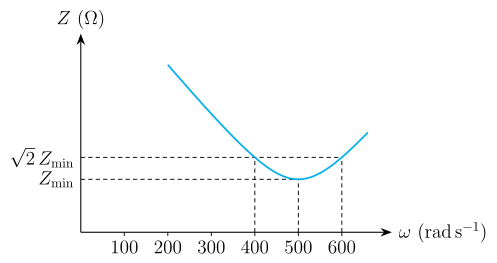
- KCET 2023Set A-31 markMCQQ.Total impedance of a series LCR circuit varies with angular frequency of the AC source connected to it as shown in the graph. The quality factor Q of the series LCR circuit is
 (A) 2.5
(B) 5
(C) 1
(D) 0.4
(A) 2.5
(B) 5
(C) 1
(D) 0.4›Reveal solutionSolution
Recognise the 2Zmin crossings as the half-power (bandwidth) frequencies, then use Q=Δωω0.
1. Why 2Zmin marks the half-power points
For a series LCR circuit,
Z(ω)=R2+(ωL−ωC1)2
At resonance the reactances cancel (ω0L=1/ω0C), leaving the minimum impedance
Zmin=Ratω0=LC1
The graph shows this minimum at ω0=500 rads−1.
The half-power points ω1,ω2 are where the power dissipated falls to half its resonant value. Since P=Z2Vrms2R, halving P means Z2=2R2, i.e.
Z=2R=2Zmin
That is precisely the upper dashed line on the graph. So the two frequencies where the curve crosses it,
ω1=400 rads−1,ω2=600 rads−1,
are the half-power frequencies. (Equivalently, the current there is Imax/2.)
2. Bandwidth
Δω=ω2−ω1=600−400=200 rads−1
3. Quality factor
Q=Δωω0=200500=2.5 …
- COMEDK 2023Set 2023-E1 markMCQQ.The current sensitivity of a galvanometer having 20 divisions is 10μA/ div. If the resistance of the galvanometer is 100Ω then the value of the resistance to be used to convert this galvanometer in to an voltmeter to read up to 1 V is : (A) 4×10⁻⁶Ω in series with the galvanometer. (B) 4900Ω in parallel with the galvanometer. (C) 4×10⁻³Ω in series with the galvanometer. (D) 4900Ω in series with the galvanometer.
›Reveal solutionSolution
So a 4900 ohm resistance is connected IN SERIES with the galvanometer. (A parallel resistance would make an ammeter, so (B) is wrong; the tiny values in (A)/(C) are shunt-like and far too small.)
Concept: converting a galvanometer into a voltmeter - connect a HIGH resistance R in SERIES, chosen so that the full-scale current Ig produces the desired full-scale voltage V:
V = Ig (G + R) => R = V/Ig - G.
Step 1 - full-scale current:
Ig = (current sensitivity) x (number of divisions) = 10 uA/div x 20 div = 200 uA = 2 x 10^-4 A.
Step 2 - series resistance for V = 1 V, G = 100 ohm:
R = 1 / (2 x 10^-4) - 100 = 5000 - 100 = 4900 ohm. …
- KCET 2022Set B-31 markMCQQ.When a metal conductor connected to left gap of a meter bridge is heated, the balancing point (A) Remains unchanged (B) Shifts to the center (C) Shifts towards right (D) Shifts towards left
›Reveal solutionSolution
Metals have a positive temperature coefficient, so heating raises the left-gap resistance; the metre-bridge balance condition then demands a longer left-hand length, i.e. the null point slides right.
Step 1 — The balance condition.
A metre bridge is a Wheatstone bridge whose two lower arms are the two parts of a uniform 1 m wire. With R in the left gap and S in the right gap, and the jockey balanced at a distance l (in cm) from the left end, the resistances of the wire segments are proportional to their lengths, so
SR=100−ll.
Step 2 — What heating does to a metal.
For a metallic conductor,
RT=R0[1+αΔT],α>0.
Heating makes the lattice ions vibrate more vigorously, so conduction electrons are scattered more often; the relaxation time τ falls and, since ρ=ne2τm, the resistivity — and hence R — increases. (This is the key difference from a semiconductor, where more carriers are freed and R falls.)
Step 3 — Track the balance point.
S (right gap) is untouched, so the ratio R/S increases. Therefore 100−ll must increase. Since this fraction is a strictly increasing function of l, the new balancing length l must be larger than before — the null point is found further from the left end, i.e. it shifts towards the right. …
🎓Unlock everything free for 14 days
- ✓Full step-by-step solutions
- ✓Concept-first explanations
- ✓Methods, shortcuts & mistakes
- ✓PYQ mapping + timed mock tests
Full access for 14 days. No credit card required.