Physics · Ch 9 — Current Electricity
Metre Bridge
Metre Bridge
The basic Wheatstone-bridge circuit of Section 9.3 is used, in practice, in several different physical forms, each built to determine some unknown resistance conveniently and precisely. The bridge is also used more broadly for measuring very low resistances with precision, and, in related configurations, for measuring quantities such as a galvanometer's own resistance, capacitance, inductance and impedance -- sometimes together with an operational amplifier, for measuring physical parameters like temperature or strain electrically.
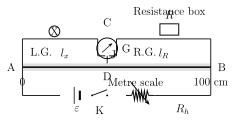
The metre bridge is the most common laboratory form of the Wheatstone bridge. It replaces two of the four bridge arms with a single uniform resistance wire, exactly one metre long, stretched taut along a metre scale that is fixed to a wooden base board. Both ends of this wire are soldered beneath two L-shaped metallic strips, one at each end of the scale, and a third, single metallic strip is fixed between these two L-shaped strips, splitting the space above the wire into a LEFT gap and a RIGHT gap. Conventionally, the unknown resistance X is connected across the left gap, and a resistance box (supplying a known, adjustable resistance) is connected across the right gap. One terminal of a galvanometer is permanently wired to the central strip, while its other terminal ends in a movable contact called a jockey, which the experimenter taps at different points directly on the exposed wire.
To use it: a suitable resistance R is selected on the resistance box, and the jockey is tapped at various points along the wire AB until a point D is found where the galvanometer shows NO deflection -- this D is the balance point, or null point. Writing for the length of wire between end A and D, and for the remaining length between D and the other end, the bridge is balanced exactly when the ratio of the two wire-segment resistances equals the ratio of the unknown to the known resistance, i.e.
Since the wire is uniform, each segment's resistance is proportional to its own length: with the wire's resistivity and A its cross-sectional area, and , so the area and resistivity cancel out of the ratio, leaving simply
With R known and both lengths , measured directly off the metre scale, the unknown resistance X follows at once from Eq. (9.9) -- this is the metre bridge's basic use, illustrated numerically in Ex. 9.5, where a series pair of 2 \Omega and 3 \Omega is measured against the bridge's own 1.49 \Omega wire resistance to also find the current drawn from the driving cell and the specific resistance of the wire's own material. …
Drawn by us to help you understand the concept clearly, and verified to make sure it's accurate. For exams, practice from your textbook's own diagram.
What this figure shows. A one-metre-long resistance wire of uniform cross-section, stretched taut along a metre scale fixed to a wooden table, with its two ends soldered beneath two L-shaped metallic strips at either end of the scale. A third, single metallic strip sits between the two L-shaped strips, splitting the region above the wire into a left gap and a right gap: the unknown resistance X is connected across the left gap and a resistance box is connected across the right gap, both bridging from the central strip to their respective end strip. A galvanometer has one terminal permanently connected to the central strip C, while its other terminal ends in a jockey (J) that the experimenter taps at different points along the exposed wire to find the null point …
Worked out. A 2 \Omega and a 3 \Omega resistor are connected in series across one gap of a metre bridge, whose own wire has resistance 1.49 \Omega and diameter 0.12 cm; the problem asks for the current through the driving cell when the bridge is balanced and for the specific resistance (resistivity) of the bridge-wire material. Since the bridge is balanced, the 2 \Omega+3 \Omega series pair (total ) sits in parallel, as seen by the driving cell, with the bridge wire's own total resistance (): their parallel combination is . Using the book's own worked value of a 2 V driving cell (implied by its printed arithmetic, even though the cell's emf is not legible in the extracted stem), the current drawn is A. The wire's resistivity follows from with cm and m, giving m. The book separately discusses the metre bridge's practical error sources -- non-uniform wire cross-section, unaccounted contact resistance where the wire is soldered to the end strips, and inaccuracy in reading the two lengths -- and how to minimise them: keep the null point in the wire's middle third (34 cm to 66 cm) so the percentage error in both measured lengths stays small and nearly equal, repeat the experiment with X and the resistance box swapped between the two gaps, and always TAP the jockey rather than sliding it, since sliding can scratch/damage the wire and change its resistanc …
Worked out. A dedicated arrangement for finding a galvanometer's own resistance G using the same metre-bridge circuit: the galvanometer (whose resistance is to be found) is connected in one gap and a known resistance box R in the other. Procedure: with a suitable value set on the resistance box, the key is closed and the circuit's steady deflection is noted WITHOUT touching the jockey anywhere on the wire; the rheostat is adjusted so this deflection is around two-thirds of full scale; the jockey is then tapped at different points along the wire until a point D is found where the galvanometer shows NO CHANGE in its deflection whether or not the jockey touches the wire there -- since an unchanging deflection means no current flows between B and D through the jockey, points B and D must be at the same potential, i.e. this is the balance point exactly as in an ordinary metre-bridge measurement. Writing for the wire-length opposite the galvanometer arm and for the length opposite the resistance-box arm, the balance condition gives , letting the otherwise hard-to-measure resistance o …
Worked out. A Post Office (PO) Box packages the four Wheatstone-bridge arms into resistance plugs inside one instrument: two ratio arms, P and Q, each provide fixed resistances of 10, 100 or 1000 \Omega (selectable by removing the appropriate plug), a third arm R is adjustable anywhere from 1 \Omega to 5000 \Omega, and the fourth arm is the unknown resistance X -- typically a wire -- whose value is sought. Two tap keys, and , control the battery and galvanometer circuits respectively. With P and Q fixed at a convenient ratio, R is adjusted until the galvanometer shows no deflection, i.e. the bridge is balanced, at which point the unknown resistance follows directly from the ordinary Wheatstone balance condition rearranged as . If the unknown is itself a wire of length L and radius r, its material's specific resistance follows as -- exactly the same resistivity formula used for the metre-bridge …
Worked out. Strain gauges are resistive elements (commonly in the 30 \Omega to 3000 \Omega range) whose electrical resistance changes in proportion to the mechanical strain applied to them; because a given strain typically changes the resistance by only a small fraction of its full range, measuring that small change accurately needs a Wheatstone-bridge configuration rather than a plain ohmmeter. In the arrangement described, two of the bridge's four arms, and , are made equal to each other, the third arm is a variable resistor (a rheostat), and the fourth arm is the strain gauge itself in place of an ordinary unknown resistor. With no force applied to the gauge, is adjusted until a voltmeter across the galvanometer diagonal shows zero deflection -- the bridge is balanced, and this null condition is taken as the gauge's own strain-free zero. When the gauge is subsequently stretched or compressed, its resistance changes, unbalancing the bridge and producing a voltmeter reading proportional to the amount of strain (larger applied strain gives a larger voltage difference across the meter terminals, while zero strain restores the balanced, zero-reading co …