Physics · Ch 9 — Current Electricity
Wheatstone Bridge
Wheatstone Bridge
Many physical quantities besides a wire's own material and geometry can shift the value of a resistance -- temperature, mechanical strain, humidity, the level of a liquid, and more all change how much a given resistor resists current. Because of this, measuring one of THOSE quantities accurately can often be turned into the (easier) problem of measuring a resistance accurately, provided the resistance-measuring method itself is precise enough. Depending on the expected size of the resistance -- anywhere from a few milliohms up to hundreds of megohms -- different measurement methods suit different ranges; the Wheatstone bridge, in particular, is the standard method for resistances from roughly a few tens of ohms up to a few hundred ohms.
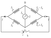
The Wheatstone bridge circuit was originally developed by Charles Wheatstone (1802-1875) to measure unknown resistances, and it is also used to calibrate other measuring instruments such as voltmeters and ammeters. Four resistances -- call them P, Q, R and S -- are wired to form a quadrilateral (a four-sided closed loop) ABCD. A battery of emf , in series with a key, is connected across ONE diagonal of this quadrilateral (A to C), with point A held at the higher potential; a sensitive galvanometer of internal resistance G is connected across the OTHER diagonal (B to D).
When the key is closed, a total current I enters the bridge at A and splits into two parts: through arm P (towards B) and through arm S (towards D), so that
At B, splits further: a current flows through the galvanometer branch (from B to D), while the rest, , continues on through arm Q. Meanwhile at D, the current arriving from S combines with the galvanometer current, so that flows on through arm R; both paths then recombine at C, on their way back to the battery.
Applying Kirchhoff's voltage law (clockwise) to loop A-B-D-A gives
and applying it (clockwise) to loop B-C-D-B gives
A special, very useful case arises when the galvanometer carries NO current at all, ; the bridge is then said to be BALANCED, and this balance can always be reached by suitably adjusting P, Q, R and S. Substituting into Eqs. (9.4) and (9.5) gives, respectively,
Dividing Eq. (9.6) by Eq. (9.7) eliminates both branch currents entirely, leaving the famous balance (or bridge) condition, purely in terms of the four resistances:
…
Drawn by us to help you understand the concept clearly, and verified to make sure it's accurate. For exams, practice from your textbook's own diagram.
What this figure shows. Four resistances P, Q, R and S are connected to form a quadrilateral ABCD: P between A and B, Q between B and C, R between C and D, and S between D and A (this is the standard labelling the balance condition is derived against, with P and S meeting at A). A battery of emf in series with a key is connected across the diagonal A-C, with A at the higher potential, so that when the key is closed a total current I enters at A and splits into (through P, into B) and (through S, into D). A galvanometer of internal resistance G bridges the OTHER diagonal, B to D; the current arriving at B further splits, with a fraction flowing through the galvanometer from B to D and the remainder continuing through Q toward C, while at D the current arriving from S combines with so t …
Worked out. A Wheatstone bridge has one variable resistor Q and the other three arms fixed; the problem asks at what value Q must be set for the bridge to balance, and then -- with the source voltage across the battery diagonal given as 30 V -- what the output voltage across the galvanometer diagonal (labelled X-Y) works out to once balanced. Applying the balance condition (equivalently ) to the three known fixed resistances gives the required k\Omega. The second part is really a consistency check rather than a fresh calculation: by the very definition of a balanced bridge (galvanometer current ), points X and Y sit at exactly the same potential no matter what the individual arm values are, so the output voltage across X-Y is necessarily 0 V -- which the book confirms by separately computing the potential of each point along both arms of the bridge (each branch's own potential-divider drop, e.g. using ) and finding both come out …