Physics · Ch 4 — Thermodynamics
The Heat Engine Cycle and the p-V Diagram
The Heat Engine Cycle and the p-V Diagram
A heat engine's repeating cycle is a well-defined sequence of operations and, being a cyclic process, can be represented on a p-V diagram exactly as described generally in Section 4.7.3.6. Heat is absorbed during one part of the cycle, work is done during another part, and the unused, leftover heat is rejected during yet another part.
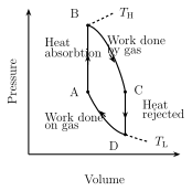
A typical heat engine cycle can be walked through in four stages, around a closed p-V loop with corner states labelled , , , :
A to B — heat absorbed at constant volume. The working substance (the gas) absorbs heat while its volume is held fixed; no work is done by or on the gas during this stage (Section 4.7.3.4). The gas's pressure rises, and — since but heat is being added — its temperature and internal energy rise as well.
B to C — expansion, work done. The gas now expands, pushing the piston outward; its volume rises from B's volume to C's volume, and correspondingly its pressure falls. The gas does positive work on the piston during this stage.
C to D — heat rejected at constant volume. At point C, the excess heat that was not used to do work is rejected to the cold reservoir; this again happens at constant volume, so no work is done, but the gas cools and its pressure falls further as its internal energy decreases.
D to A — compression, cycle closes. Finally, the gas is compressed: its volume decreases and its pressure rises, continuing until the system returns exactly to state A, ready to begin the next cycle. …
Drawn by us to help you understand the concept clearly, and verified to make sure it's accurate. For exams, practice from your textbook's own diagram.
What this p-V diagram shows. The graph plots pressure p (vertical axis) against volume V (horizontal axis); the area under the curve equals the work done during the process, and the shape of the path tells you how pressure and volume change tog …