Q.The given circuit has two ideal diodes D1 and D2 connected as shown in the figure: a resistor R1=3 Ω in series with a 10 V source, feeding a node that splits into two parallel branches -- diode D1 in series with R2=2 Ω, and diode D2 in series with R3=2 Ω -- both diodes oriented so they are forward biased by the 10 V source. Calculate the current flowing through the resistance R1.
Concept understanding — Diode Resistance Calculation
Diode Resistance: What Does It Even Mean?
Think of a diode as a one-way valve for electricity. When you push current through it in the forward direction, the diode doesn't just let everything through freely — it resists the flow, just like any other component. But here's the twist: that resistance isn't a fixed number like a resistor's 100 Ω. It changes depending on how much voltage you apply.
Why? Because a diode is a semiconductor device. Its current-voltage relationship follows the Shockley equation:
I=IS(eV/ηVT−1)
where IS is the reverse saturation current, V is the applied voltage, η is the ideality factor (usually 1 for silicon), and VT≈26 mV at room temperature.
This exponential curve means that a tiny change in voltage can cause a huge change in current. So the "resistance" you measure depends entirely on where you are on that curve.
Two Kinds of Diode Resistance
Because the I-V curve is nonlinear, we define two different resistances — each useful in different situations.
1. Static (DC) Resistance
This is the simplest idea: just apply Ohm's law using the total voltage and total current at a given operating point.
RDC=IV
For example, if a diode has 0.7 V across it and 10 mA flowing through it, its DC resistance is:
RDC=0.010.7=70 Ω
Static resistance tells you the average opposition to current at that specific point. It's useful for power calculations (P=I2RDC) but not for small signal analysis.
2. Dynamic (AC) Resistance
This is the more important one for circuit design. It tells you how the diode responds to small changes in voltage around a fixed operating point.
Mathematically, dynamic resistance is the slope of the I-V curve at that point:
rd=dIdV
For a forward-biased diode obeying the Shockley equation, we can derive a clean formula. Starting from:
I=ISeV/ηVT
(ignoring the -1, which is negligible in forward bias)
Differentiate:
dVdI=ηVTI
Therefore:
rd=dIdV=IηVT
rd=IηVT
At room temperature with η=1 and VT=26 mV:
rd=I26 mV
So if the diode current is 10 mA, rd=2.6 Ω — much smaller than the 70 Ω DC resistance.
Dynamic resistance is not a physical resistor inside the diode. It's a small-signal model parameter. You cannot use it with DC voltages or large signals — only for tiny variations around the operating point.
When Do You Use Each?
| Situation | Use |
|---|---|
| Finding DC power dissipation | RDC |
| Designing a biasing circuit | RDC |
| Analyzing small-signal amplifier response | rd |
| Calculating voltage regulation in a Zener diode | rd (called Zener impedance) |
A Quick Example to Tie It Together
A silicon diode (η=1) is forward biased with V=0.7 V and carries I=20 mA.
Static resistance:
RDC=0.020.7=35 Ω
Dynamic resistance:
rd=20 mA26 mV=1.3 Ω
If the voltage changes by a tiny ±10 mV around 0.7 V, the current change will be approximately:
ΔI≈rdΔV=1.3 Ω10 mV≈7.7 mA
The DC resistance would have predicted only ΔI=10/35≈0.29 mA — completely wrong for small signals.
The Bottom Line
Diode resistance is not one number — it's two. Static resistance handles the big picture (total voltage and current), while dynamic resistance handles the fine details (how the diode reacts to small fluctuations). Both are essential, and confusing them is one of the most common mistakes students make.
Always ask yourself: Am I working with DC values or small AC changes? That question tells you which resistance to use.
Static and dynamic diode resistance calculations are a regularly tested numerical type in the NCERT Class 12 Physics chapter on Semiconductor Electronics, and "diode resistance formula AC and DC" is a common search among students preparing for CBSE boards and JEE Main. This distinction between the two resistances is also a favourite conceptual trap in "semiconductor electronics important questions" compiled for competitive-exam practice.
Why this formula?
Diode Resistance: Why It Changes with Operating Point
A diode is not a linear resistor. Its current-voltage relationship follows the Shockley equation:
I=IS(eV/ηVT−1)
where IS is the reverse saturation current, η is the ideality factor (typically 1–2), and VT=kT/q≈26mV at room temperature.
Because the I–V curve is exponential, the diode's resistance depends entirely on where you are on that curve. There are two distinct resistances we care about: DC resistance (static) and AC resistance (dynamic).
DC Resistance (Static Resistance)
Definition: The ratio of the DC voltage across the diode to the DC current through it at a given operating point.
RDC=IV
Why this formula? It's simply Ohm's law applied to the DC values. If you put 0.7 V across a diode and get 10 mA through it, the DC resistance is 0.7/0.01=70Ω. But this number is misleading — it doesn't tell you how the diode responds to a small change in voltage.
DC resistance is rarely useful in circuit analysis because diodes are never operated as fixed resistors. It's just a snapshot at one point.
AC Resistance (Dynamic Resistance)
Definition: The slope of the I–V curve at a given operating point — i.e., the ratio of a small change in voltage to the resulting small change in current.
rd=dIdV
Why this formula? For small signals (like an AC voltage superimposed on a DC bias), the diode behaves approximately linearly around that bias point. The dynamic resistance is the local slope of the I–V curve.
Now let's derive the actual expression.
Derivation of rd=IηVT
Start from the Shockley equation. For forward bias where V≫VT, the −1 term is negligible:
I≈ISeV/ηVT
Take the derivative with respect to V:
dVdI=IS⋅ηVT1⋅eV/ηVT=ηVTI
The dynamic resistance is the reciprocal:
rd=dIdV=IηVT
rd=IηVT
Key insight: The dynamic resistance is inversely proportional to the DC current I. At higher currents, the diode's I–V curve is steeper, so a small voltage change produces a larger current change — meaning lower resistance.
Why This Matters
- At low currents (e.g., I=1mA), rd≈26Ω (for η=1). The diode acts like a moderate resistor.
- At high currents (e.g., I=100mA), rd≈0.26Ω. The diode is almost a short circuit for small AC signals.
This is why a diode's AC resistance is not a fixed number — it changes with the bias current. In circuits like rectifiers, clippers, or voltage regulators, you always calculate rd at the actual operating current.
For quick estimates at room temperature, use rd≈26mV/I (assuming η=1). For silicon diodes with η≈2, double it: rd≈52mV/I.
Summary of the Two Resistances
| Resistance Type | Formula | What It Tells You |
|---|---|---|
| DC (static) | RDC=V/I | Overall resistance at a fixed DC point |
| AC (dynamic) | rd=ηVT/I | How the diode responds to small signal changes |
The dynamic resistance is the one you'll use in almost every exam problem involving small-signal analysis of diode circuits.
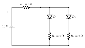
With both ideal diodes forward biased, the two 2 ohm branches combine in parallel to 1 ohm, adding to the series 3 ohm resistor for a total of 4 ohm across the 10 V supply.
I=2.5 A
Step 1. Since both diodes D1 and D2 are oriented to be forward biased by the 10 V source, treat them as ideal closed switches (zero resistance, zero voltage drop).
Step 2. With both diodes conducting, the two branches D1-R2 (2 Ω) and D2-R3 (2 Ω) are in PARALLEL: R23=(2×2)/(2+2)=1 Ω.
Step 3. This parallel combination is in series with R1=3 Ω, giving a total circuit resistance Rtotal=3+1=4 Ω.
Step 4. By Ohm's law, the current through R1 (which carries the full circuit current, since it is the series element) is I=V/Rtotal=10/4=2.5 A.
I=2.5 A
Treat both ideal diodes as closed switches, combine the two parallel 2 ohm branches, then apply Ohm's law.
- Forgetting that R1 carries the FULL current (it is in series with the parallel combination), not just a share of it.
- Adding R2 and R3 in series instead of recognising their parallel arrangement.
- CBSE 2026Set 55/3/11 markMCQQ.When the forward bias voltage in a semiconductor diode is changed from 0.8 V to 1.0 V, the forward current changes by 2.0 mA. The forward bias resistance of the diode will be : (A) 200 Ω (B) 175 Ω (C) 100 Ω (D) 125 Ω
›Reveal solutionSolution
The forward bias resistance (dynamic resistance) is the ratio of change in voltage to change in current. Here, ΔV=0.2 V and ΔI=2.0 mA, so rd=0.2/(2.0×10−3)=100 Ω. The correct option is (C).
The key idea here is that a diode does not obey Ohm’s law — its current-voltage relationship is exponential. So when we talk about “forward bias resistance,” we don’t mean a fixed resistance like in a resistor. Instead, we mean the dynamic resistance (also called AC resistance or small-signal resistance), which tells you how much the current changes for a small change in voltage around a given operating point.
Why does this matter? Because in exam problems like this, they give you a change in voltage and the corresponding change in current — that’s exactly the definition of dynamic resistance:
rd=ΔIΔV
Let’s apply it step by step.
-
Identify the given data
Initial voltage: V1=0.8 V
Final voltage: V2=1.0 V
Change in voltage: ΔV=V2−V1=1.0−0.8=0.2 V
Change in current: ΔI=2.0 mA=2.0×10⁻³ A
-
Apply the formula for dynamic resistance
rd=ΔIΔV=2.0×10−30.2
- Calculate
rd=0.0020.2=100 Ω
Watch outA common mistake is to use the absolute voltage and current values (like 0.8 V/I) instead of the change. That would give the static (DC) resistance, which is different and not what the question asks. The phrase “forward bias resistance” in such problems always refers to dynamic resistance when a change is given.
TipIf the numbers feel messy, rewrite 2.0 mA as 0.002 A immediately. Then 0.2/0.002=200/2=100 — a clean result.
✓Final answerThe forward bias resistance of the diode is 100 Ω, which corresponds to option (C).
-
- CBSE 2023Set ANNUAL1 markMCQQ.On increasing the forward voltage of a forward biased p-n junction diode, its junction resistance :(a) increases(b) decreases(c) remains unchanged(d) None of these
›Reveal solutionSolution
Increasing the forward voltage decreases the junction resistance of a diode.
Under forward bias the depletion region narrows and the current rises steeply and non-linearly with voltage. Because the current increases faster than the voltage, the dynamic (junction) resistance dV/dI keeps falling as the forward voltage rises. This non-ohmic behaviour is central to the diode I–V curve in the NCERT/CBSE Class 12 semiconductor chapter.
✓Final answer(b) decreases.
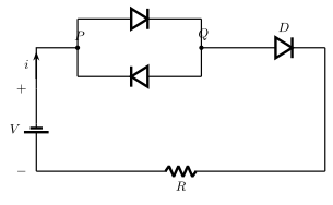
- CBSE 2018Set ANNUAL1 markQ.Find the current i in the circuit given below. Given, forward resistance of the diode is rf=1Ω, R=2Ω and V=10 volts.
›Reveal solutionSolution
Two diodes stacked in opposite (anti-parallel) directions between the same pair of nodes mean that whichever way current tries to flow through that pair, one of the two always blocks it — so the branch carries no current regardless of the applied EMF.
Circuit description
The battery V drives current through resistor R on the bottom wire. This connects to a node from which two diodes are drawn between the same two nodes, but pointing in opposite directions to each other; a third diode is then in series on the way back to the battery.
Reasoning
Consider the pair of anti-parallel diodes: for current to pass through that section in either direction, it must go through one of the two diodes. But since they point opposite ways, whichever direction the current tries to flow, exactly one of the two diodes is reverse-biased for that direction and blocks it (an ideal diode conducts in only one direction). This means no current can pass through that pair of diodes at all, in either direction — the anti-parallel pair acts as an open circuit.
Since this pair lies in the single available path around the loop (in series with the third diode, R, and the battery), the entire loop is broken, and:
i=0
irrespective of the values of rf, R and V given.
✓Final answeri=0 — the anti-parallel diode pair blocks current in both directions, so no current can flow anywhere in this loop.
🎓Unlock everything free for 14 days
- ✓Full step-by-step solutions
- ✓Concept-first explanations
- ✓Methods, shortcuts & mistakes
- ✓PYQ mapping + timed mock tests
Full access for 14 days. No credit card required.