Physics · Ch 7 — System of Particles and Rotational Motion
What Kind of Motion Can a Rigid Body Have?
What Kind of Motion Can a Rigid Body Have?
Opening the Question
Before we can analyse the motion of a rigid body, we must first understand what kinds of motion are even possible for it. A rigid body is not a point particle — it has size, shape, and an internal structure that stays fixed. This immediately opens up possibilities that a point particle never had.
Consider a rectangular block. You can slide it across a table without tilting it — every point moves in parallel straight lines. That is pure translational motion. You can also spin it about a fixed axis, like a rotating door — that is pure rotational motion. But most real motions are a combination of both: a rolling wheel, for instance, translates forward while rotating about its centre.
The textbook classifies the possible motions of a rigid body into three distinct types. Each type is defined by what happens to the body's orientation and to the positions of its individual particles.
Type 1: Pure Translational Motion
In pure translation, every particle of the rigid body undergoes exactly the same displacement in the same direction over the same time interval. The body's orientation does not change — a line drawn on the body remains parallel to its original direction throughout the motion.
Because all particles move identically, the motion of the entire body is completely described by the motion of any single point — usually the centre of mass.
Mathematically, if is the position vector of the -th particle at time , and is its initial position, then for pure translation:
where is the same vector function for every particle . Differentiating once gives the velocity: every particle has the same instantaneous velocity . Differentiating again gives the same acceleration for all particles.
A car moving along a straight road without any tilt or rotation is a familiar example. The chassis, the passengers, the luggage — every point moves forward by the same distance in the same time.
Type 2: Pure Rotational Motion
In pure rotation, every particle of the rigid body moves in a circle about a fixed axis. The axis itself is stationary in space. The body's orientation changes continuously — a line drawn on the body no longer stays parallel to its original direction.
The key geometric fact is this: all particles share the same angular velocity (magnitude of angular speed) and the same angular acceleration , but their linear velocities differ depending on their distance from the axis.
If a particle is at a perpendicular distance from the axis of rotation, its linear speed is related to the angular speed by:
The direction of the linear velocity is always tangential to the circular path. The acceleration has two components: a tangential component and a centripetal (radial) component .
Do not confuse the angular velocity (same for all particles) with the linear velocity (different for different particles). A point on the rim of a rotating wheel moves much faster than a point near the hub, even though both complete one revolution in the same time.
A ceiling fan rotating about its central axle, with the motor housing fixed, is a pure rotation. The blades sweep out circles, but the centre of the fan does not move from its position.
Type 3: Combined Translational and Rotational Motion
This is the most general case. The body translates and rotates simultaneously. A rolling bicycle wheel is the classic example: the wheel's centre moves forward (translation), while the wheel spins about its centre (rotation). The orientation of the wheel changes, and different points on the wheel have different net velocities — some move faster than the centre, some slower, and the point in contact with the ground is instantaneously at rest (if rolling without slipping).
In this type of motion, the body's centre of mass follows some path (not necessarily straight), and the body rotates about an axis that passes through the centre of mass (or about some other point, depending on the situation). The general motion can always be decomposed into a translation of the centre of mass plus a rotation about the centre of mass.
This decomposition — translation of the centre of mass plus rotation about the centre of mass — is a fundamental principle. It holds for any rigid body motion, no matter how complicated. The two parts are independent and can be analysed separately.
The Three Properties of Rigid Body Motion
The textbook then states three formal properties that summarise the above classification. Each property is a precise statement about what kind of motion is possible.
Property (I): A rigid body can have pure translational motion.
Proof/derivation: This follows directly from the definition of a rigid body. Since the distances between all particles are fixed, if one particle moves along a straight line, every other particle must move along a parallel straight line by exactly the same amount — otherwise the distances would change. Therefore the entire body translates as one unit. No rotation occurs; the orientation remains unchanged throughout.
Property (II): A rigid body can have pure rotational motion about a fixed axis.
Proof/derivation: Fix a line in space (the axis). Constrain every particle of the body to move only in circles whose centres lie on this axis and whose planes are perpendicular to it. Because the body is rigid, the angular displacement about the axis is the same for all particles. Consequently the angular velocity and angular acceleration are also the same for all particles. The linear displacement of any particle is , its linear speed is , and its tangential acceleration is , where is the perpendicular distance from the axis. The axis itself does not move.
Property (III): A rigid body can have motion that is a combination of translation and rotation. …
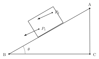
Drawn by us to help you understand the concept clearly, and verified to make sure it's accurate. For exams, practice from your textbook's own diagram.
The figure shows a right triangle with vertices labelled B, C, and A. The right angle is at C, so the side BC is vertical and CA is horizontal. The hypotenuse BA is the inclined plane, sloping down from B to A. A square block rests on this incline, and two points on the block are marked: P₁ near the top edge and P₂ near the bottom edge. Two arrows of equal length, parallel to BA, point down the incline from P₁ and P₂. These arrows represent the instantaneous velocity of each point.
The physical idea is straightforward: when a rigid body slides without rotating, every point in the body moves with the same velocity at any given instant. The block is not tumbling or spinning — it is simply translating down the slope. The two velocity arrows are identical in length and direction because P₁ and P₂, though at different heights on the block, are both moving with the same speed and in the same direction at that moment. This is the hallmark of pure translational motion: the entire body shifts as a unit, so the velocity of any point is the same as the velocity of the centre of mass.
The figure does not show rotation. If the block were rolling or tipping, the velocity arrows at P₁ and P₂ would differ in either magnitude or direction. The equal parallel arrows are the visual signature of pure translation.
The textbook uses this figure to introduce the idea that a rigid body can move in more than one way — translation, rotation, or a combination of both. For pure translation, the key result is that the velocity of every particle in the body is identical:
Here , , etc. are the velocities of individual particles (or points like P₁ and P₂), and is the velocity of the centre of mass. The equality holds at every instant during pure translational motion.
This simple observation leads directly to the formula for the total kinetic energy of a translating rigid body. Since every particle has the same speed , the kinetic energy of the -th particle is , and summing over all particles gives:
where is the total mass of the body. So for pure translation, the kinetic energy is exactly the same as if the entire mass were concentrated at the centre of mass moving with speed . …
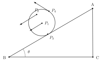
Drawn by us to help you understand the concept clearly, and verified to make sure it's accurate. For exams, practice from your textbook's own diagram.
Figure 6.2 is a snapshot of a cylinder rolling down an incline. The incline is drawn as a simple right-triangle, with the cylinder shown as a circle resting on the slope at a single point of contact, labelled P₃. Four points on the cylinder are marked: the centre of the circle is P₁, the topmost point is P₂, a point on the upper-right side is P₄, and the point in contact with the incline is P₃. From each of these points, an arrow is drawn to represent the instantaneous velocity of that point. The arrows are of different lengths: the arrow at P₃ has zero length — it is just a dot — while the arrows at P₁, P₂, and P₄ are progressively longer, with P₂’s arrow being the longest.
The physical idea is that in pure rolling (no slipping), the point of the cylinder that touches the ground is instantaneously at rest relative to the ground. That is why the velocity arrow at P₃ is zero. The centre P₁ has some translational velocity; P₂, P₃, and P₄ each combine that translational motion with the body’s rotation about its centre, so their velocities differ from P₁’s and from each other — exactly what the different arrow lengths in the figure show.
This figure is the key evidence that rolling is not pure translational motion — if it were, every point would carry the same velocity arrow, just like in Fig. 6.1. Instead, the four arrows have different lengths, proving that rolling motion is translation plus something else — which the chapter goes on to identify as rotation.
A common mistake is to think that the point of contact is “at rest” because it is not moving relative to the ground — that is correct — but then to incorrectly conclude that friction does no work. In pure rolling, static friction at the contact point does no work because the point has zero instantaneous velocity, but friction still provides the torque needed to start or change the rolling motion. The figure’s zero arrow at P₃ is the visual proof that the contact point is instantaneously stationary. …
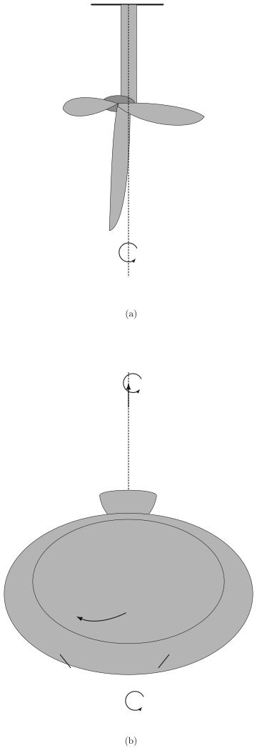
Drawn by us to help you understand the concept clearly, and verified to make sure it's accurate. For exams, practice from your textbook's own diagram.
Fig. 6.3 is a simple pair of sketches that makes the idea of rotation about a fixed axis concrete. In panel (a) you see a ceiling fan: a central hub with four blades, all mounted on a vertical dashed line that represents the fan’s support rod. A curved arrow around that line shows the direction in which the fan rotates. In panel (b) you see a potter’s wheel: a thick disk sitting on a vertical spindle, again with a curved arrow indicating rotation. In both cases every point of the rigid body (the fan blades or the wheel) moves in a circle around that fixed vertical line. That line is the axis of rotation, and because it does not change direction or location in space, the motion is called rotation about a fixed axis.
The physical idea is straightforward: when a rigid body rotates about a fixed axis, each particle of the body stays at a constant perpendicular distance from the axis and traces out a circular path. The entire body shares the same angular velocity and the same angular acceleration at any instant. This is what distinguishes pure rotation from translation or from more complicated motions like rolling.
The textbook uses this figure to introduce the kinematic equations for rotational motion, which are direct analogues of the linear equations you already know. For constant angular acceleration , the relations are:
Here is the initial angular velocity (in rad/s), is the angular velocity after time , is the angular displacement (in rad) during that time, and is the constant angular acceleration (in rad/s). Each symbol refers to a quantity measured about the fixed axis shown in the figure.
Do not confuse (angular displacement) with the number of revolutions. One full revolution corresponds to rad. Always work in radians when using these formulas. …
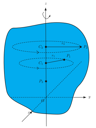
Drawn by us to help you understand the concept clearly, and verified to make sure it's accurate. For exams, practice from your textbook's own diagram.
The figure shows a rigid body — drawn as an irregular blob — rotating about a fixed vertical -axis. The origin sits at the intersection of the axis with the plane of the page. Two perpendicular axes, (pointing lower-left) and (pointing right), complete a right-handed coordinate system. The rotation arrow around the -axis indicates the sense of rotation.
Two representative points inside the body, and , are highlighted. Each lies at a different distance from the axis. As the body rotates, traces a horizontal circle of radius centred at on the axis; traces a circle of radius centred at . The dashed circles in the figure show these paths. A third point lies exactly on the axis itself — it remains stationary throughout the motion.
Every point in a rigid body rotating about a fixed axis moves in a circle whose centre lies on the axis. Points on the axis do not move at all.
The physical idea is that all particles of a rigid body share the same angular velocity , even though their linear speeds differ. For a point at perpendicular distance from the axis, the linear speed is , and the linear acceleration has a centripetal component and (if changes) a tangential component , where is the angular acceleration.
The textbook uses this figure to introduce the kinematics of rotational motion and to define the moment of inertia. For a particle of mass at distance from the axis, its contribution to the rotational inertia is . Summing over all particles gives the moment of inertia of the body:
Here is the mass of the -th particle and is its perpendicular distance from the axis of rotation. The figure makes clear that is not the distance from the origin , but the perpendicular distance from the axis — for that is , the radius of its circular path.
The rotational kinetic energy of the body follows directly:
and the torque required to produce an angular acceleration is:
…
Drawn by us to help you understand the concept clearly, and verified to make sure it's accurate. For exams, practice from your textbook's own diagram.
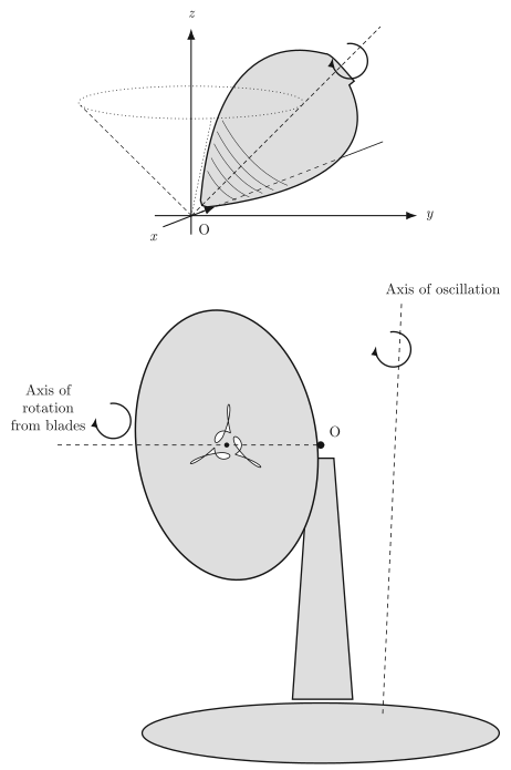
Figure 6.5 in the NCERT textbook is a two-panel illustration that answers a deceptively simple question: what kinds of motion can a rigid body have? The answer is not just "rotation" — a rigid body can spin around an axis that itself moves. That is the core idea both panels are built to show.
Panel (a) shows a spinning top. The tip of the top is fixed at point O, and the body of the top is tilted away from the vertical. The dashed lines trace out a cone around the vertical -axis — this is the precession cone. The top spins rapidly about its own symmetry axis, but that axis is not fixed in space; it slowly sweeps around the vertical, tracing the cone. The and axes are drawn in the horizontal plane, and a curved arrow around the vertical indicates the direction of precession. So the top has two simultaneous rotations: a fast spin about its own axis (the body's rotation) and a slow rotation of that axis itself about the vertical (precession). The fixed point O is the only point of the body that does not move.
Panel (b) shows a table fan whose blades rotate about a horizontal axis — that is the "Axis of rotation from blades" drawn as a horizontal dashed line. But the entire fan assembly, including that horizontal axis, can tilt up and down. The vertical dashed line labelled "Axis of oscillation" shows the direction about which the fan's head oscillates. The pivot point O is where the fan's neck meets the base. So the blades spin rapidly about one axis, while that axis itself rocks back and forth about a perpendicular axis through O. Again, two distinct motions happen at once.
The physical idea is that a rigid body can have more than one rotation simultaneously, and these rotations can be about different axes that are not fixed relative to each other. The top's spin axis precesses; the fan's spin axis oscillates. In both cases, exactly one point of the body stays fixed (the tip O of the top, the pivot O of the fan) — even though no single line through the body stays fixed the way it does for the ceiling fan and potter's wheel of Fig. 6.3.
This is exactly why the chapter narrows its scope right after this figure: analysing a body whose axis itself is moving is considerably more involved than analysing rotation about a genuinely fixed axis. The textbook states plainly that, from this point on, it will consider rotational motion about a fixed axis only — the simpler, special case shown in Fig. 6.3 and Fig. 6.4, not the more general precessing/oscillating motion shown here. …
Drawn by us to help you understand the concept clearly, and verified to make sure it's accurate. For exams, practice from your textbook's own diagram.
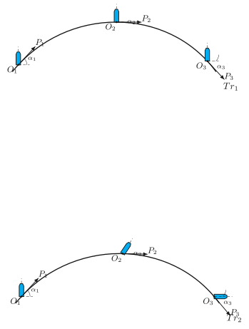
The figure shows two rows of three snapshots of a rigid body moving from left to right. In each snapshot the body is drawn as a short line segment with a dot at one end (the dot is labelled O, the other end P). The path of O is drawn as a smooth curve labelled Tr₁, and the path of P as a second curve labelled Tr₂. The three positions of the body are labelled O₁, O₂, O₃ (and correspondingly P₁, P₂, P₃). The angles that the segment OP makes with the horizontal at each position are marked α₁, α₂, α₃.
In panel (a) — labelled "Pure translation" — the three angles are equal: α₁ = α₂ = α₃. The segment OP slides without rotating; every point of the body traces a curve parallel to every other point’s curve. In panel (b) — labelled "Combination of translation and rotation" — the angles are different: α₁ ≠ α₂ ≠ α₃. The segment OP both moves forward and turns, so the two trajectories Tr₁ and Tr₂ are no longer parallel curves.
The physical idea is the fundamental decomposition of rigid-body motion. A rigid body can move in only two ways: it can translate (every point moves by the same displacement in the same time, so the orientation of any line fixed in the body stays constant), or it can rotate (the body turns about some axis). Any general motion is a superposition of these two — a translation of the centre of mass plus a rotation about the centre of mass. The figure makes this concrete: in pure translation the orientation of OP is preserved; in the general case the orientation changes, and the motion is a combination of translation and rotation.
The key formula that the textbook develops from this idea is the relation between the velocities of two points on a rigid body. If O is the centre of mass and P is any other point, then
…